3 Installation | Model 3300TB | |
|
|
|
|
|
|
|
|
|
Analog Outputs: There are three DC output signal connectors with screw terminals on the panel. There are two wires per output with the polar- ity noted. See Figure
Voltage rises with increasing oxygen concentration, | |
| from 0 V at 0 percent oxygen to 10 V at full scale |
| percent oxygen. (Full scale = 100% of programmed |
| range.) |
03.33 V = Low Range, 06.66 V = High Range, | |
| 10 V = Air Cal Range. |
Current increases with increasing oxygen concentra- | |
| tion, from 4 mA at 0 percent oxygen to 20 mA at full |
| scale percent oxygen. (Full scale = 100% of pro- |
| grammed range.) |
Alarm Relays: The three
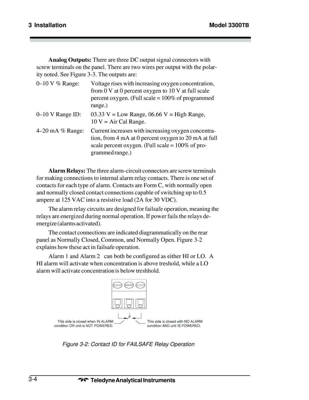
The alarm relay circuits are designed for failsafe operation, meaning the relays are energized during normal operation. If power fails the relays de- energize (alarms activated).
The contact connections are indicated diagrammatically on the rear panel as Normally Closed, Common, and Normally Open. Figure
Alarm 1 and Alarm 2 can both be configured as either HI or LO. A HI alarm will activate when concentration is above treshold, while a LO alarm will activate concentration is below treshhold.
Figure 3-2: Contact ID for FAILSAFE Relay Operation
Teledyne Analytical Instruments |