Using the BayStack 350 10/100 Autosense Switch
Table
Table |
| |
|
|
|
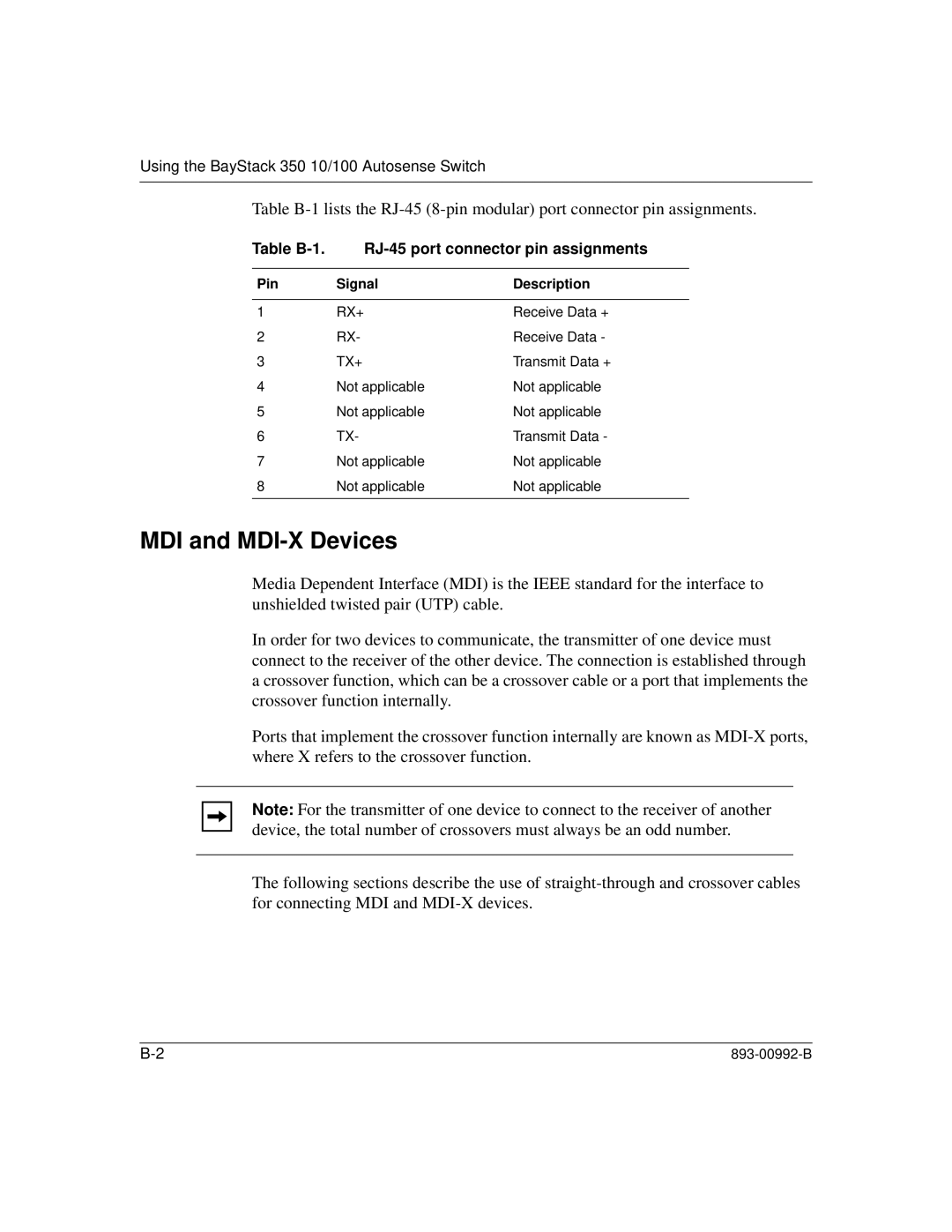
Pin | Signal | Description |
|
|
|
1 | RX+ | Receive Data + |
2 | RX- | Receive Data - |
3 | TX+ | Transmit Data + |
4 | Not applicable | Not applicable |
5 | Not applicable | Not applicable |
6 | TX- | Transmit Data - |
7 | Not applicable | Not applicable |
8 | Not applicable | Not applicable |
|
|
|
MDI and MDI-X Devices
Media Dependent Interface (MDI) is the IEEE standard for the interface to unshielded twisted pair (UTP) cable.
In order for two devices to communicate, the transmitter of one device must connect to the receiver of the other device. The connection is established through a crossover function, which can be a crossover cable or a port that implements the crossover function internally.
Ports that implement the crossover function internally are known as
Note: For the transmitter of one device to connect to the receiver of another device, the total number of crossovers must always be an odd number.
The following sections describe the use of