Installation
Verifying the Installation
To verify proper operation of the BayStack 350 switch, observe the
Table 2-1. Power-up sequence
Stage Description | LED indication |
1Immediately after AC power is applied to the switch, DC power is available to the switch’s internal circuitry.
The Power LED turns on within 5 seconds (Figure
If the Power LED does not turn on, verify that power is available at the AC power outlet and that the power cable is fastened securely at both ends.
If the Power LED remains off, contact the sales agent or the customer service representative from whom you purchased the BayStack 350 switch.
2 | The switch initiates | As subroutines are initiated by the |
| a | LEDs flash various patterns. When the switch passes the |
|
| |
|
| (Figure |
If a nonfatal error occurs during the
Diagnostics LED blinks.
If the switch fails the
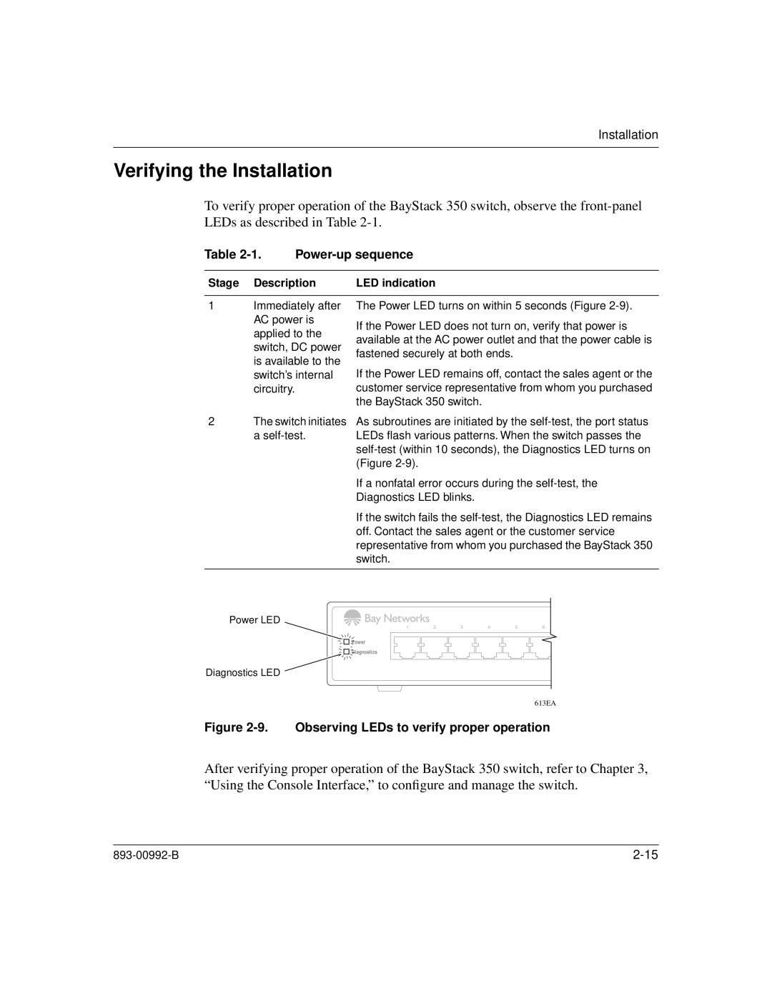
Power LED
Diagnostics LED
1 | 2 | 3 | 4 | 5 | 6 |
Power |
|
|
|
|
|
Diagnostics |
|
|
|
|
|
613EA
Figure 2-9. Observing LEDs to verify proper operation
After verifying proper operation of the BayStack 350 switch, refer to Chapter 3, “Using the Console Interface,” to configure and manage the switch.