Using the BayStack 350 10/100 Autosense Switch
Port Statistics
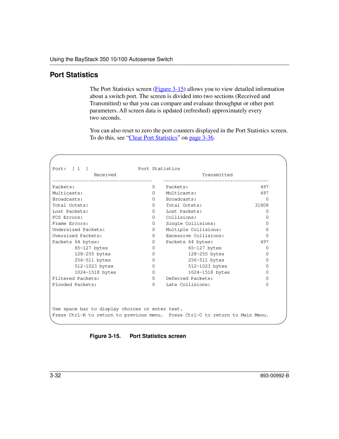
The Port Statistics screen (Figure
two seconds.
You can also reset to zero the port counters displayed in the Port Statistics screen. To do this, see “Clear Port Statistics” on page
Port: [ 1 ] | Port Statistics |
| |
Received |
| Transmitted |
|
Packets: | 0 | Packets: | 497 |
Multicasts: | 0 | Multicasts: | 497 |
Broadcasts: | 0 | Broadcasts: | 0 |
Total Octets: | 0 | Total Octets: | 31808 |
Lost Packets: | 0 | Lost Packets: | 0 |
FCS Errors: | 0 | Collisions: | 0 |
Frame Errors: | 0 | Single Collisions: | 0 |
Undersized Packets: | 0 | Multiple Collisions: | 0 |
Oversized Packets: | 0 | Excessive Collisions: | 0 |
Packets 64 bytes: | 0 | Packets 64 bytes: | 497 |
0 | 0 | ||
0 | 0 | ||
0 | 0 | ||
0 | 0 | ||
0 | 0 | ||
Filtered Packets: | 0 | Deferred Packets: | 0 |
Flooded Packets: | 0 | Late Collisions: | 0 |
Use space bar to display choices or enter text.
Press