Manuals
/
RAD Data comm
/
Computer Equipment
/
Modem
RAD Data comm
ASMI-450
operation manual
ASMi-450 Internal Settings
Models:
ASMI-450
1
35
117
117
Download
117 pages
38.23 Kb
32
33
34
35
36
37
38
39
Troubleshooting
Specifications
Hdsl Subsystem Characteristics
Install
Error codes
Alarms
Password
Fault Indications
Control or Indicator Function
Appendix a Connector Wiring
Page 35
Image 35
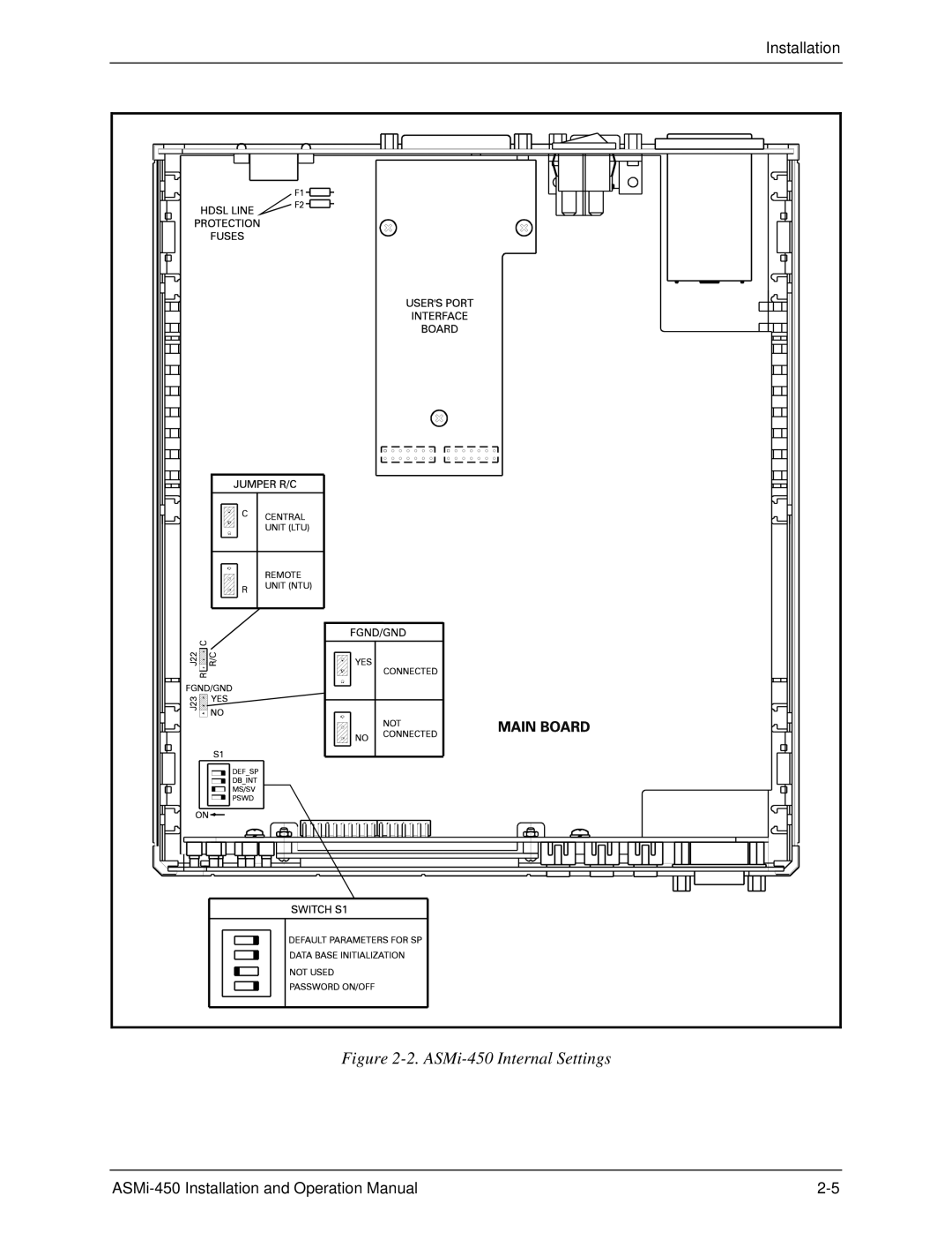
Installation
Figure
2-2.
ASMi-450
Internal Settings
ASMi-450
Installation and Operation Manual
2-5
Page 34
Page 36
Page 35
Image 35
Page 34
Page 36
Contents
ASMi-450
Warranty
Hdsl
Selv
Regulatory Information
Declaration of Conformity
Page
Contents
ASMi-450 Control from the Control Port
Appendix a Connector Wiring
Contents
List of Figures
List of Figures Xii
List of Tables
List of Tables Xiv
Preliminary Preparations Starting Procedure
Starting the Configuration
Function Terminal Type TV920 VT52 VT100 Freedom 100/110
Configuration Procedure
Step Action Use the Command
Type Configuration Display Commands Control Commands
Command Index
Quick-Start Guide
Functional Description
Purpose and Main Features
Typical Application for ASMi-450 with Data Interface
Hdsl Subsystem Characteristics
Internal timing
System Timing
Remote Management
Control ASMi-450 Operation
Local Control
Introduction
Power Requirements
Test and Diagnostics Capabilities
Alarms
Physical Characteristics
Operating Environment
Transmission Media Hdsl Line Signal
Binary Digits Quaternary Symbol
Hdsl Signal Structure HDSL-Related System Functions
Hdsl Interface
Technical Specifications
Ethernet Interface
Physical Characteristics
General
Chapter Installation
Site Requirements
Unpacking
Opening ASMi-450 Case
ASMi-450 Configuration Information
General
Switch S1
Jumper and Switch Location Functions
ASMi-450 Internal Settings
OFF
Jumper FGND/GND
Internal Settings Procedure Reinstalling ASMi-450 Cover
Jumper R/C
Connector Location Grounding
DC Power Connection
Power Connection Users Port Connections
AC Power Connection
Hdsl Line Connections Control Port Connection
Scope
Chapter Front-Panel Operating Instructions
Control or Indicator Function
Front Panel Controls, Connectors, and Indicators
Ethernet Interface
Indicators
Indicator Function
General General Operating Instructions Display Functions
Control of ASMi-450 Operation, General
Display Description See
Configuration Parameters
Status Messages
Test Functions
Push-buttons
Using Front-Panel
Organization
ASMi-450 Display
Front-Panel Operating Instructions
Designation Function Values
System Configuration Parameters
Control Port Configuration Parameters
Operating Instructions
Turn-on Checking Current Operating Configuration
Scroll
Display
Cursor
Ethernet Interface Indications
Fault Indications
Step Action Key Display
Normal Front-Panel Indications
Protection
Local Configuration Set-Up Procedure
Password
Configuration Procedure
Already there Scroll to display the desired group
Alarm Buffer
Specific Configuration Guidelines
SP Parameters
LCD Configuration Error Messages
Front-Panel Operating Instructions
Chapter ASMi-450 Control from the Control Port
Hardware Requirements
Clear to Send CTS
Interface Type
Data Terminal Ready DTR
Request to Send RTS
Data Set Ready DSR
Autobaud Function
Ring Indication RI
ASMi-450 Preparations Supervision Terminal Connections
Internal Settings
Control Port Configuration
Preparation for Use of Supervision Terminal
Option Meaning Example of Usage
Command Language Syntax Command Options
Command Protocol
ASMi-450 Supervision Language
Index of Commands
Command Purpose Options
Format
ASMi-450 Command Set Description
CLR ALM
CLR Loop
DEF Agent
CLR TST
Date
Display Fields
DEF Name
DEF PWD
DEF Node
Purpose Format Use
DEF SP
PWD
DEF Term
DEF SYS
Format Use
DSP ALM
Function Terminal Type VT-52 VT-100 Freedom-110
Alarm No Alarm Syntax Meaning State Time
Remote DB
Remote Alarm
Remote Signal Loss
Quality Alarm
Connected
DSP HDR TST
DSP ST Line
REM LAN not
Purpose Format Use Display Format
DSP ST Port
Display Format
Exit
DSP ST SYS
Help
Init DB
Parameter Designation Default Value
Node
Password
Loop
Time
Reset
Starting a Session Single ASMi-450
Control Session
Ending a Control Session
Configuration Error Messages
ASMi-450 Control from the Control Port
Status Indications and Messages
Indicators Display
ON/OFF
Message Description Corrective Actions Alarm
ASMi-450 Alarm Buffer Messages Cont’d
Remote Alarm
Remote Reverse
Test Functions
Test Functions
Operating Instructions
Loop REM REM Port
Activating the Test Functions from a Control Terminal
Power-Up Self-Test
Trouble Symptoms Probable Cause Corrective Measures
Troubleshooting Instructions
LAN
Pin Designation Direction Function
RS-530 DCE Connector and Adapter Cables
Rceb
Pin Designation Direction Function 36/RS-449/422
Rcea
V.35 DCE Connector
X.21 DCE Connector
Pin Line Connected Connected to To Terminal
Hdsl Line Connector
RS-232 V.24 Control Port Connector
Pin Function
Ethernet Interface Connector
Appendix B Snmp Management
Snmp Operations
Snmp Environment
General Snmp Principles
MIBs Supported by the ASMi-450 Snmp Agent
Management Information Base
MIB Structure
Snmp Communities
Access Restriction Using Snmp Communities
Management Domains Under
Read
ASMi-450 Communities
Address Class First Byte Address Range
IP Environment
General IP Environment
IP Address Structure
Snmp Management
Snmp Traps
Appendix C Installation in 19 Racks
Figure C-1. Installation of Single Unit in 19 Rack
Installation of Single Unit
General Preparations
Installation of Two Units
Fastening the Two Units
ASMi-450
To install the ferrite cores
Top
Page
Image
Contents