Front-Panel Operating Instructions
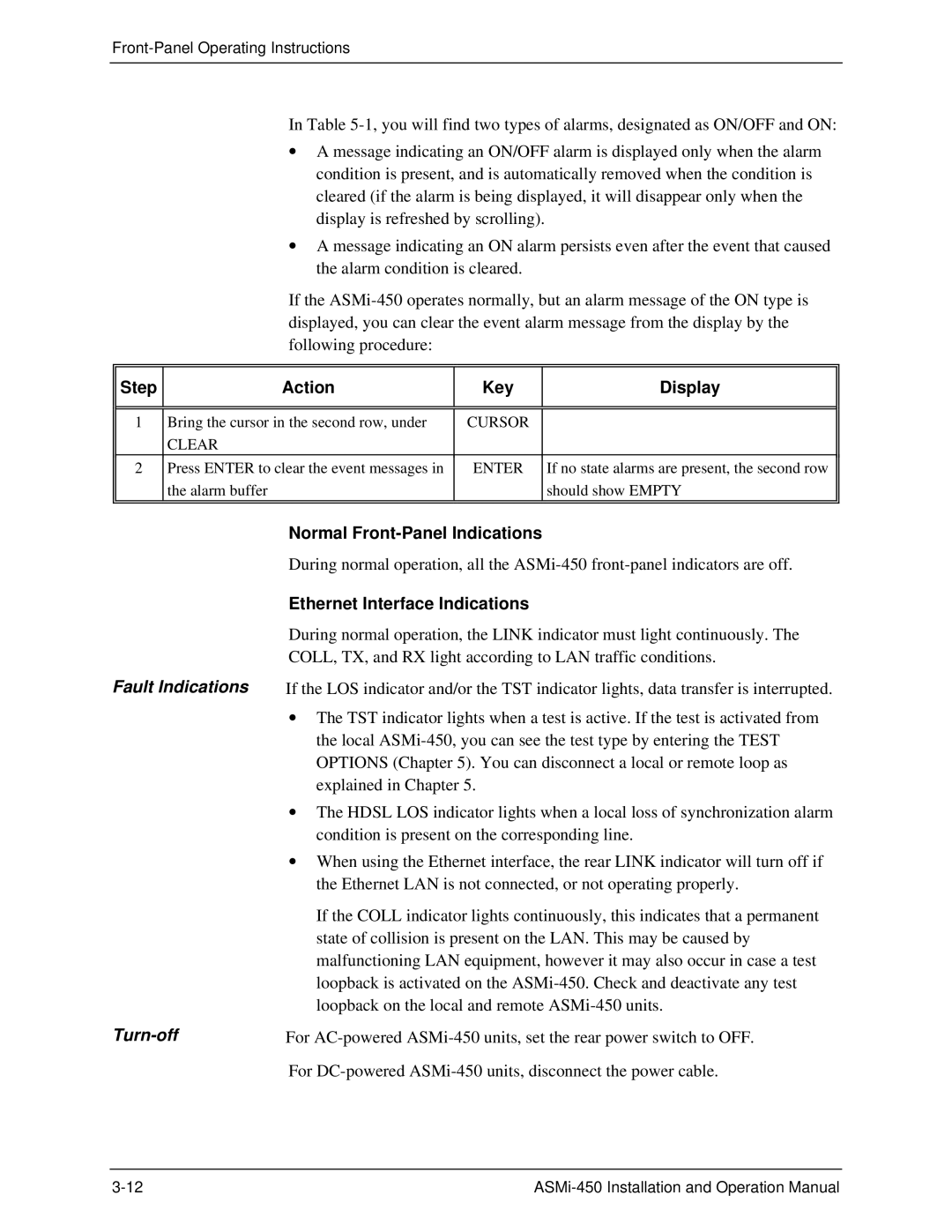
In Table
∙A message indicating an ON/OFF alarm is displayed only when the alarm condition is present, and is automatically removed when the condition is cleared (if the alarm is being displayed, it will disappear only when the display is refreshed by scrolling).
∙A message indicating an ON alarm persists even after the event that caused the alarm condition is cleared.
If the
Step | Action | Key | Display |
|
|
|
|
|
|
|
|
1 | Bring the cursor in the second row, under | CURSOR |
|
| CLEAR |
|
|
2 | Press ENTER to clear the event messages in | ENTER | If no state alarms are present, the second row |
| the alarm buffer |
| should show EMPTY |
|
|
|
|
| Normal |
| During normal operation, all the |
| Ethernet Interface Indications |
| During normal operation, the LINK indicator must light continuously. The |
| COLL, TX, and RX light according to LAN traffic conditions. |
Fault Indications | If the LOS indicator and/or the TST indicator lights, data transfer is interrupted. |
| ∙ The TST indicator lights when a test is active. If the test is activated from |
| the local |
| OPTIONS (Chapter 5). You can disconnect a local or remote loop as |
| explained in Chapter 5. |
| ∙ The HDSL LOS indicator lights when a local loss of synchronization alarm |
| condition is present on the corresponding line. |
| ∙ When using the Ethernet interface, the rear LINK indicator will turn off if |
| the Ethernet LAN is not connected, or not operating properly. |
| If the COLL indicator lights continuously, this indicates that a permanent |
| state of collision is present on the LAN. This may be caused by |
| malfunctioning LAN equipment, however it may also occur in case a test |
| loopback is activated on the |
| loopback on the local and remote |
| For |
