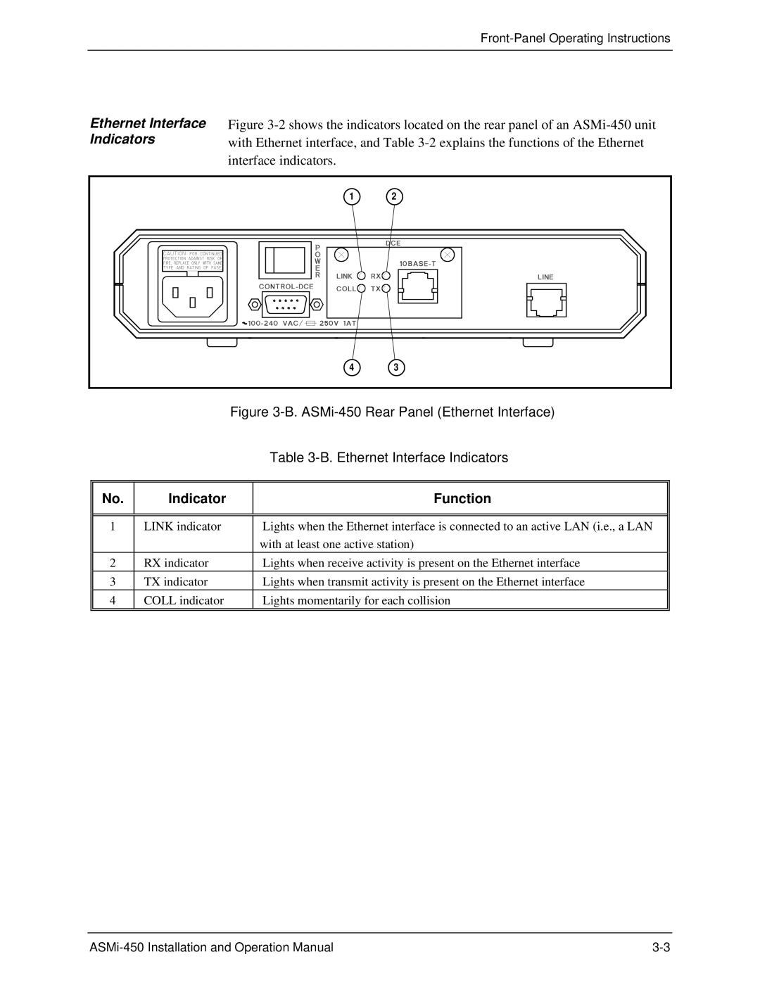
Ethernet Interface | Figure |
Indicators | with Ethernet interface, and Table |
| interface indicators. |
1 | 2 |
4 | 3 |
Figure 3-B. ASMi-450 Rear Panel (Ethernet Interface)
|
| Table |
|
|
|
No. | Indicator | Function |
|
|
|
|
|
|
1 | LINK indicator | Lights when the Ethernet interface is connected to an active LAN (i.e., a LAN |
|
| with at least one active station) |
2 | RX indicator | Lights when receive activity is present on the Ethernet interface |
3 | TX indicator | Lights when transmit activity is present on the Ethernet interface |
4 | COLL indicator | Lights momentarily for each collision |
|
|
|