Contents
Camera Revision D
CV-M30
Operation Manual
Monochrome Double Speed Camera
CV-M30
Table of Contents
1. General
3. Main Features
2. Standard Composition
CV-M30
CV-M30
4. Locations and Functions
5. Pin Assignment
5.1. 12-pin Multi-connector DC-IN/VIDEO OUT, EXT.HD/VD IN
5.2. 6-pin Multi-connector TRIGGER
Signal
Fig. 4. WEN and EEN output Fig. 5. HD and VD/Trigger input
5.3. Input and Output Diagram
CV-M30
6.3. External Trigger Mode
6.1. Input of External HD/VD Signals
6. Functions and Operations
6.2. Continuous Operation
CV-M30
6.3.1. Edge Pre-select Mode
Cautions in the Edge Pre-select Mode
CV-M30
6.3.2. Pulse Width Control Mode
Cautions in the Pulse Width Control Mode
6.4.2. Partial Scanning Mode
6.5. Timing Charts
6.4. Other Functions
6.4.1. Double Speed Mode
H = 31.778 µs
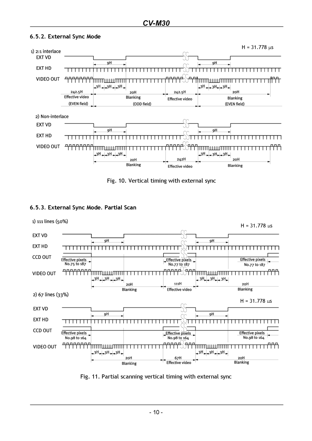
6.5.2. External Sync Mode
6.5.3. External Sync Mode. Partial Scan
CV-M30
H = 31.778 µs
6.5.4. Edge Pre-select
6.5.5. Edge Pre-select. Partial Scan
CV-M30
H = 31.778 µs
6.5.6. Pulse Width Control
6.5.7. Pulse Width. Partial Scan
CV-M30
Mode setting
7. Mode Setting
7.1. Switch SW1 on Rear Panel
7.1.2. Table for SW1 Setting
7.1.6. Trigger Mode
7.1.4. Scan Mode Settings
7.1.7. Gain Setting Switch
7.1.5. Double Speed Mode
7.2.2. Trigger Mode Select
7.2. Internal Switch and Jumper Settings
7.2.4. Internal Switch Positions
7.2.1. Trigger/VD and HD Termination
CV-M30
8. Internal Adjustments of Video Signal
VR4 is for factory adjustment only. Do not touch
Fig. 22. Outline
9. External Appearance and Dimensions
CV-M30
CV-M30
10. Specifications
10.1. Specification table
10.2. Spectral Sensitivity
V. Smear
11.1. Precautions
11.2. Typical CCD Characteristics
11. Appendix
CV-M30
Users Mode Settings Users Modifications
12. Users Record
Camera type