POWER CONNECTIONS
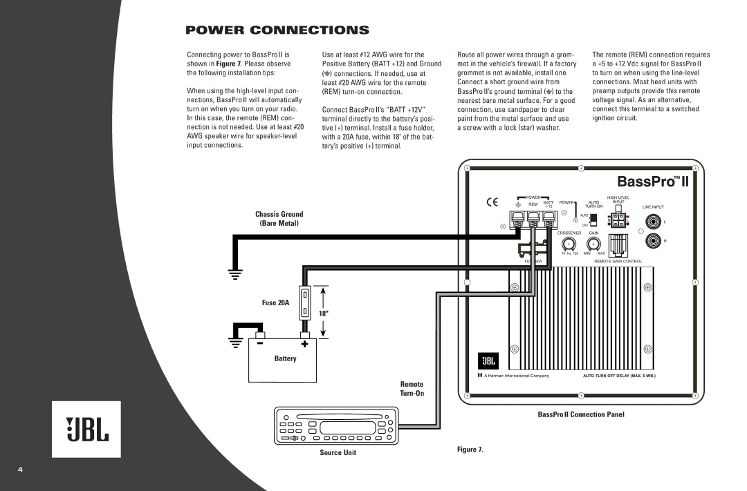
Connecting power to BassPro II is shown in Figure 7. Please observe the following installation tips:
When using the
In this case, the remote (REM) con- nection is not needed. Use at least #20 AWG speaker wire for
Use at least #12 AWG wire for the Positive Battery (BATT +12) and Ground (![]() ) connections. If needed, use at least #20 AWG wire for the remote (REM)
) connections. If needed, use at least #20 AWG wire for the remote (REM)
Connect BassPro II’s “BATT +12V” terminal directly to the battery’s posi- tive (+) terminal. Install a fuse holder, with a 20A fuse, within 18" of the bat- tery’s positive (+) terminal.
Route all power wires through a grom- met in the vehicle’s firewall. If a factory grommet is not available, install one.
Connect a short ground wire from BassPro II’s ground terminal (![]() ) to the nearest bare metal surface. For a good connection, use sandpaper to clear paint from the metal surface and use a screw with a lock (star) washer.
) to the nearest bare metal surface. For a good connection, use sandpaper to clear paint from the metal surface and use a screw with a lock (star) washer.
The remote (REM) connection requires a +5 to +12 Vdc signal for BassPro II to turn on when using the
ChassisGround (BareMetal)
(Bare
Fuse 20AA
Battery
18"
Remote
T
BassProBassProII Connection Panel
(right-side panel)
SourceUnit | Figure 7. |
|
4