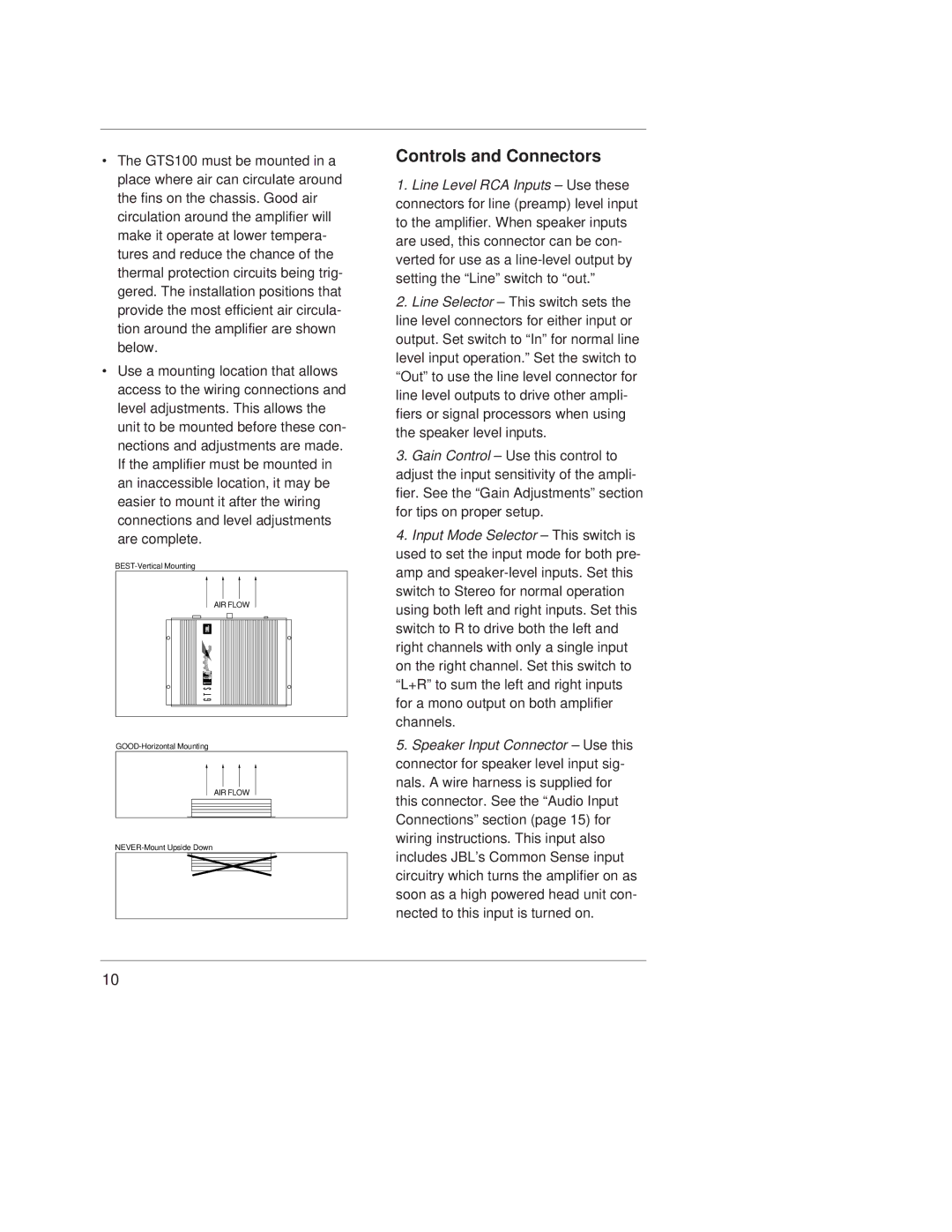
•The GTS100 must be mounted in a place where air can circulate around the fins on the chassis. Good air circulation around the amplifier will make it operate at lower tempera- tures and reduce the chance of the thermal protection circuits being trig- gered. The installation positions that provide the most efficient air circula- tion around the amplifier are shown below.
•Use a mounting location that allows access to the wiring connections and level adjustments. This allows the unit to be mounted before these con- nections and adjustments are made. If the amplifier must be mounted in an inaccessible location, it may be easier to mount it after the wiring connections and level adjustments are complete.
AIR FLOW
G T S 1 0 0
AIR FLOW
Controls and Connectors
1.Line Level RCA Inputs – Use these connectors for line (preamp) level input to the amplifier. When speaker inputs are used, this connector can be con- verted for use as a
2.Line Selector – This switch sets the line level connectors for either input or output. Set switch to “In” for normal line level input operation.” Set the switch to “Out” to use the line level connector for line level outputs to drive other ampli- fiers or signal processors when using the speaker level inputs.
3.Gain Control – Use this control to adjust the input sensitivity of the ampli- fier. See the “Gain Adjustments” section for tips on proper setup.
4.Input Mode Selector – This switch is used to set the input mode for both pre- amp and
5.Speaker Input Connector – Use this connector for speaker level input sig- nals. A wire harness is supplied for this connector. See the “Audio Input Connections” section (page 15) for wiring instructions. This input also includes JBL’s Common Sense input circuitry which turns the amplifier on as soon as a high powered head unit con- nected to this input is turned on.
10