LSR6328P Biamplified Studio Monitor System
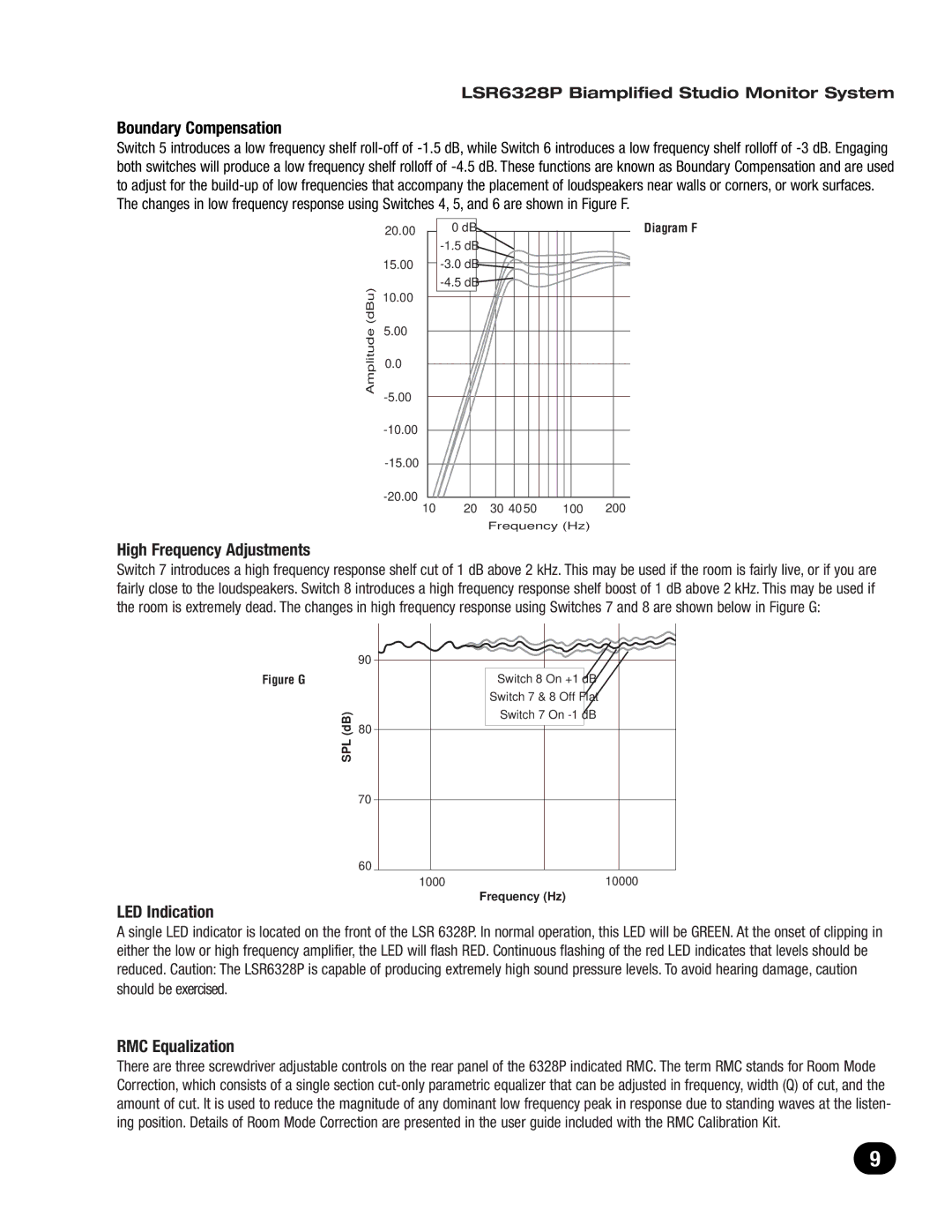
Boundary Compensation
Switch 5 introduces a low frequency shelf
The changes in low frequency response using Switches 4, 5, and 6 are shown in Figure F.
| 20.00 | 0 dB |
|
|
| Diagram F |
|
|
|
|
|
| |
| 15.00 |
|
|
|
| |
|
|
|
|
|
| |
(dBu) | 10.00 |
|
|
|
|
|
5.00 |
|
|
|
|
| |
Amplitude |
|
|
|
|
| |
0.0 |
|
|
|
|
| |
|
|
|
|
|
| |
|
|
|
|
|
| |
|
|
|
|
|
| |
|
|
|
|
|
| |
|
|
|
|
|
| |
| 10 | 20 | 30 | 40 50 | 100 | 200 |
|
|
| Frequency (Hz) |
| ||
High Frequency Adjustments
Switch 7 introduces a high frequency response shelf cut of 1 dB above 2 kHz. This may be used if the room is fairly live, or if you are fairly close to the loudspeakers. Switch 8 introduces a high frequency response shelf boost of 1 dB above 2 kHz. This may be used if the room is extremely dead. The changes in high frequency response using Switches 7 and 8 are shown below in Figure G:
| 90 |
Figure G |
|
(dB) | 80 |
SPL |
|
| 70 |
| 60 |
LED Indication
Switch 8 On +1 dB
Switch 7 & 8 Off Flat
Switch 7 On
1000 | 10000 |
Frequency (Hz)
A single LED indicator is located on the front of the LSR 6328P. In normal operation, this LED will be GREEN. At the onset of clipping in either the low or high frequency amplifier, the LED will flash RED. Continuous flashing of the red LED indicates that levels should be reduced. Caution: The LSR6328P is capable of producing extremely high sound pressure levels. To avoid hearing damage, caution should be exercised.
RMC Equalization
There are three screwdriver adjustable controls on the rear panel of the 6328P indicated RMC. The term RMC stands for Room Mode Correction, which consists of a single section
9