AIR SHUTTER ADJUSTMENT
(See Illustrations "A" and "B"):
This appliance is shipped from the factory with air shutters adjusted for use with Natural Gas. If further adjustment is necessary, or to reset for use with LP, adjustair shutters as followed:
A. SURFACE BURNER AIR SHUTTERS (See Illustration "A"):
Loosen fastening screw with a Phillips screwdriver and rotate air shutter to increase or decrease the size of the
airflameopenappearaning. As cethe. shutteAdjustrmentis turned,is satisfactoryobserve chwangehen ina clearly defined, even blue flame results at the high flame setting. After adjustment, tighten screw.
SURFACEAIR SHUTTERBURNER | ROTATEAIRTERONSHU | |
_ |
| MIXER HEAD TO |
_ | _C..RFW | MAKEAIR |
",._ | _ | ADJUSTMENT |
| AIR SHUTTER |
"__'_ |
|
AIR OPENI_'_JlB | TO |
TO _" | CLOSE |
OPEN |
|
ILLUSTRATION "A"
B. GRILL BURNER AIR SHUTTERS (See Illustration "B")
The left hand air shutter controls the rear half of the grill Jurner. The right hand shutter controls the front half.
Slide air shutter backward or forward to increase or de- crease the size of the air opening. Air shuttersfit snugly on the grill burner, so a screwdriver blade may be required to make this adjustment (see illustration).
Observe change in flame appearance as the air shutter is
moved. Adjustment is satisfactory when a clearly defined, even blue flame results at the high flame setting. The snug
fit of the air shutter assures it will remain positioned cor- rectly.
_GRtLL BURNER AIR SHUTTER
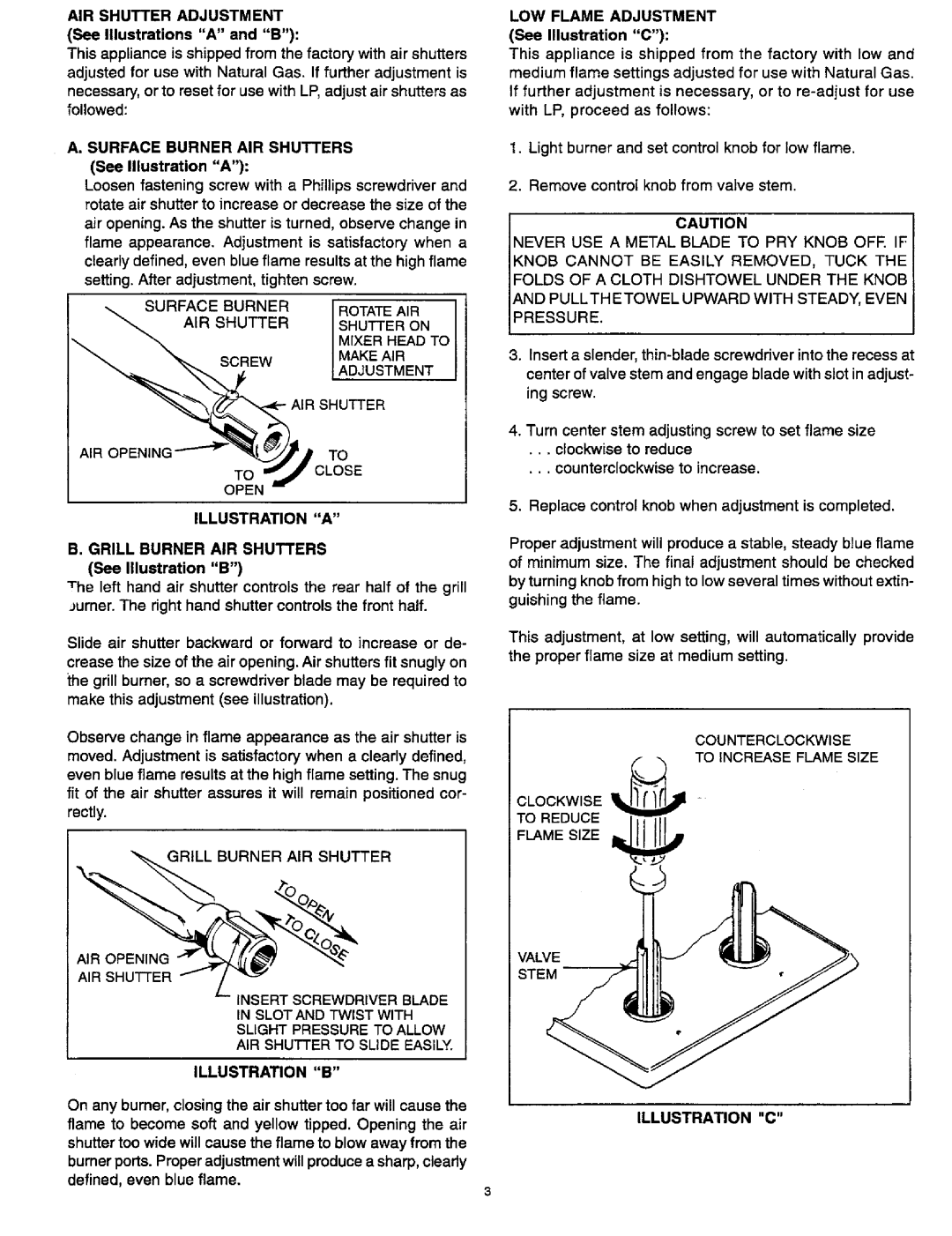
LOW FLAME ADJUSTMENT
(See Illustration "C"):
This appliance is shipped from the factory with low and medium flame settings adjusted for use with Natural Gas. If further adjustment is necessary, or to
1. Light burner and set control knob for low flame.
2. Remove control knob from valve stem.
NEVER USE A METAL CAUTIONBLADE TO PRY KNOB OFF. IF KNOB CANNOT BE EASILY REMOVED, TUCK THE I FOLDS OF A CLOTH DISHTOWEL UNDER THE KNOB
ANDPRESSUREPULLTHETOWEL.UPWARD W TH STEADY, EVEN
3. Insert a slender,
ing screw.
4.Turncenterstemadjustingscrewtosetflamesize
...clockwise to reduce
... counterclockwise to increase.
5.Replace control knob when adjustment is completed.
Proper adjustment will produce a stable, steady blue flame of minimum size. The final adjustment should be checked bytuming knob from high to Iowseveral times without extin- guishing the flame.
This adjustment, at low setting, will automatically provide the proper flame size at medium setting.
COUNTERCLOCKWISE
f
CLOCKWISE
TO REDUCE
FLAME SIZE _ | _ |
A,ROPEN,NG | VALVE |
AIR SHUTTER | STEM |
/ |
|
INSERT SCREWDRIVER BLADE |
|
IN SLOTAND TWIST WITH |
|
SLIGHT PRESSURE TO ALLOW |
|
AIR SHUTTER TO SLIDE EASILY. |
|
ILLUSTRATION "B" |
|
On any burner, closing the air shutter too far will cause the |
|
flame to become soft and yellow tipped. Opening the air | ILLUSTRATION "C" |
shutter too wide will cause the flame to blow away from the |
|
burnerports. Proper adjustmentwill producea sharp, clearly |
|
defined, even blue flame. | 3 |
|