WALL PLATE INSTALLATION
1.The wall plate/power supply assembly may be mounted in most electrical outlet/switch boxes. The plate can also be mounted without an electrical box. This mounting method requires a hole 2.75” x 2.0”. Route 2 16AWG wires to this hole from the 12VDC source. Also route all coax cables to this hole. See Figure 5.
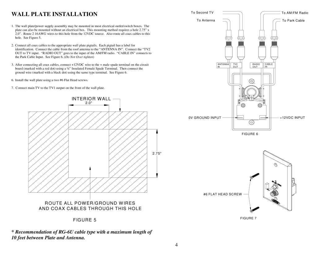
2.Connect all coax cables to the appropriate wall plate pigtails. Each pigtail has a label for identification. Connect the cable from the roof antenna to the “ANTENNA IN”. Connect the “TV2 OUT to TV input. “RADIO OUT” goes to the input of the AM/FM radio. “CABLE IN” connects to the Park Cable Input. See Figure 6. (Do Not Over tighten)
3.After connecting all coax cables, connect +12VDC wire to the + male spade terminal on the circuit board (marked with a red dot) using a ¼” Insulated Female Spade Terminal. Then connect the ground wire (marked with a black dot) using the same type terminal. See Figure 6.
6.Install the wall plate using a two #6 Flat Head screws.
7.Connect main TV to the TV1 output on the front of the wall plate.
INTERIOR WALL
2.0" |
2.75" |
ROUTE ALL POWER/GROUND W IRES
AND COAX CABLES THROUGH THIS HOLE
FIGURE 5
*Recommendation of
To Second TV | To AM/FM Radio |
To Antenna | To Park Cable |
ANTENNA | TV2 | RADIO | CABLE |
IN | O UT | OUT | IN |
0V GROUND INPUT |
|
| +12VDC INPUT |
FIGURE 6
#6 FLAT HEAD SCREW
FIGURE 7
4