ANTENNA INSTALLATION
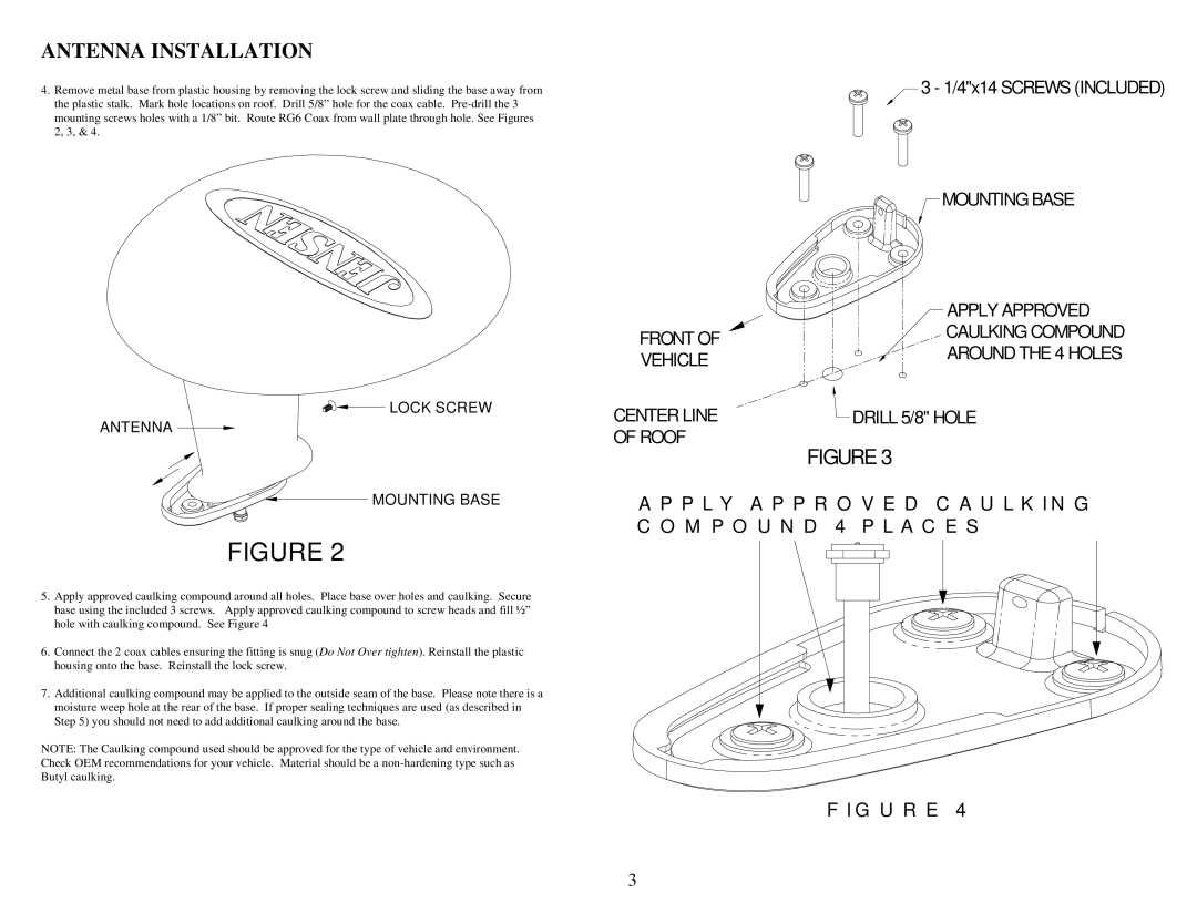
4.Remove metal base from plastic housing by removing the lock screw and sliding the base away from the plastic stalk. Mark hole locations on roof. Drill 5/8” hole for the coax cable.


 LOCK SCREW
ANTENNA 
FRONT OF VEHICLE
CENTER LINE OF ROOF
3 - 1/4"x14 SCREWS (INCLUDED)
![]() MOUNTING BASE
MOUNTING BASE
APPLY APPROVED
CAULKING COMPOUND
AROUND THE 4 HOLES
![]() DRILL 5/8" HOLE
DRILL 5/8" HOLE
FIGURE 3
 MOUNTING BASE
FIGURE 2
5.Apply approved caulking compound around all holes. Place base over holes and caulking. Secure base using the included 3 screws. Apply approved caulking compound to screw heads and fill ½” hole with caulking compound. See Figure 4
6.Connect the 2 coax cables ensuring the fitting is snug (Do Not Over tighten). Reinstall the plastic housing onto the base. Reinstall the lock screw.
7.Additional caulking compound may be applied to the outside seam of the base. Please note there is a moisture weep hole at the rear of the base. If proper sealing techniques are used (as described in Step 5) you should not need to add additional caulking around the base.
NOTE: The Caulking compound used should be approved for the type of vehicle and environment. Check OEM recommendations for your vehicle. Material should be a
A P P L Y A P P R O V E D C A U L K I N G C O M P O U N D 4 P L A C E S
F I G U R E 4
3