VM9423
USING THE TFT MONITOR
Open/Close TFT Monitor
Open TFT Monitor
Press the OPEN/CLOSE button (1) on the front panel or
press the ( ![]()
![]()
![]() ) button (25) on the remote control to slide the monitor down and reveal the disc and SD card slots.
) button (25) on the remote control to slide the monitor down and reveal the disc and SD card slots.
Close TFT Monitor
Press the OPEN/CLOSE button (1) on the front panel or
press the ( ![]()
![]()
![]() ) button (25) on the remote control close the monitor panel.
) button (25) on the remote control close the monitor panel.
Monitor Tilt Angle Adjustment
A known characteristic of LCD panels is the quality of the display in relationship to the viewing angle. The monitor angle can be adjusted for optimum viewing using one of the following methods.
Step by Step Angle Adjustment
Press the (![]() ) or (
) or (![]() ) button on the remote control (26, 27) to adjust the tilt angle of the screen one step at a time.
) button on the remote control (26, 27) to adjust the tilt angle of the screen one step at a time.
You can also adjust the tilt by pressing and holding the OPEN button (1) on the front panel. Use the up/down joystick buttons to adjust the angle of the screen while the red tilt icon is flashing.
Continuous Angle Adjustment
Press and hold the (![]() ) or (
) or (![]() ) button on the remote control to adjust the tilt angle in a continuous motion.
) button on the remote control to adjust the tilt angle in a continuous motion.
Reverse Driving Use
If the
If the monitor is in display mode, the monitor automatically switches to CAMERA mode upon reverse driving. When the reverse driving stops, the monitor returns to its original input mode.
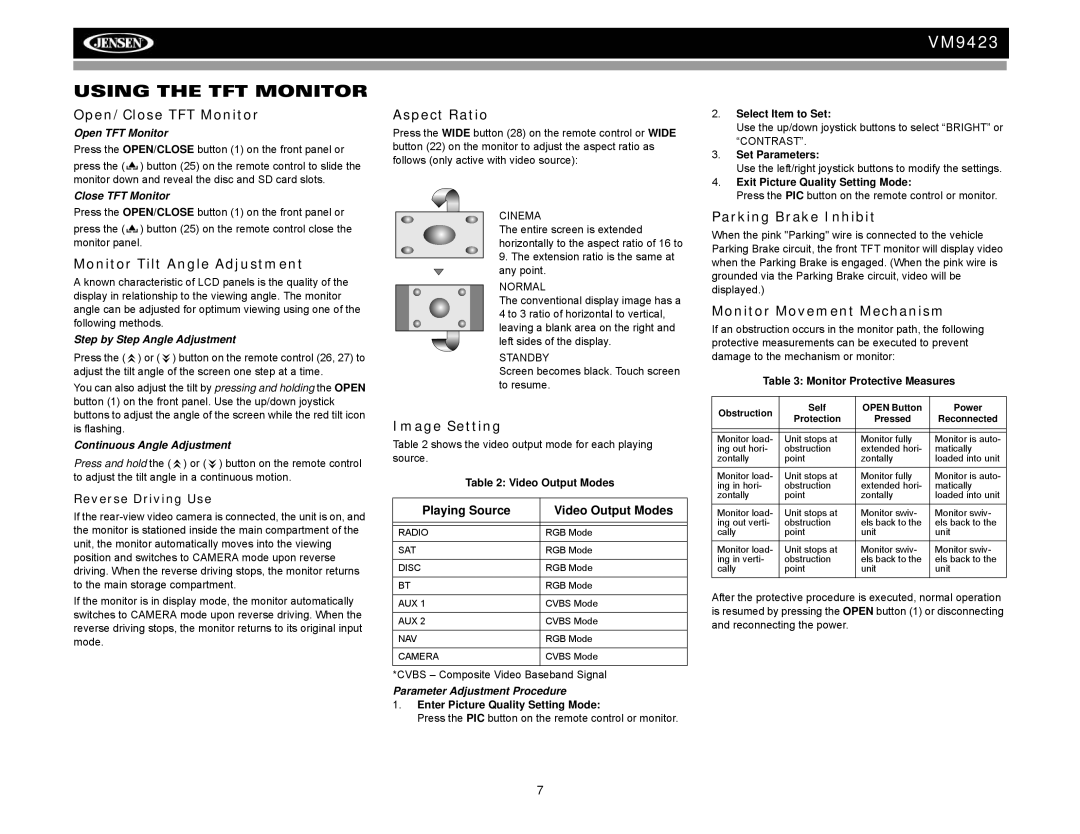
Aspect Ratio
Press the WIDE button (28) on the remote control or WIDE button (22) on the monitor to adjust the aspect ratio as follows (only active with video source):
CINEMA
The entire screen is extended horizontally to the aspect ratio of 16 to 9. The extension ratio is the same at any point.
NORMAL
The conventional display image has a 4 to 3 ratio of horizontal to vertical, leaving a blank area on the right and left sides of the display.
STANDBY
Screen becomes black. Touch screen to resume.
Image Setting
Table 2 shows the video output mode for each playing source.
Table 2: Video Output Modes
Playing Source | Video Output Modes |
|
|
|
|
RADIO | RGB Mode |
|
|
SAT | RGB Mode |
|
|
DISC | RGB Mode |
|
|
BT | RGB Mode |
|
|
AUX 1 | CVBS Mode |
|
|
AUX 2 | CVBS Mode |
|
|
NAV | RGB Mode |
|
|
CAMERA | CVBS Mode |
|
|
*CVBS – Composite Video Baseband Signal
Parameter Adjustment Procedure
1.Enter Picture Quality Setting Mode:
Press the PIC button on the remote control or monitor.
2.Select Item to Set:
Use the up/down joystick buttons to select “BRIGHT” or “CONTRAST”.
3.Set Parameters:
Use the left/right joystick buttons to modify the settings.
4.Exit Picture Quality Setting Mode:
Press the PIC button on the remote control or monitor.
Parking Brake Inhibit
When the pink "Parking" wire is connected to the vehicle Parking Brake circuit, the front TFT monitor will display video when the Parking Brake is engaged. (When the pink wire is grounded via the Parking Brake circuit, video will be displayed.)
Monitor Movement Mechanism
If an obstruction occurs in the monitor path, the following protective measurements can be executed to prevent damage to the mechanism or monitor:
Table 3: Monitor Protective Measures
Obstruction | Self | OPEN Button | Power | |
Protection | Pressed | Reconnected | ||
| ||||
|
|
|
| |
|
|
|
| |
Monitor load- | Unit stops at | Monitor fully | Monitor is auto- | |
ing out hori- | obstruction | extended hori- | matically | |
zontally | point | zontally | loaded into unit | |
Monitor load- | Unit stops at | Monitor fully | Monitor is auto- | |
ing in hori- | obstruction | extended hori- | matically | |
zontally | point | zontally | loaded into unit | |
Monitor load- | Unit stops at | Monitor swiv- | Monitor swiv- | |
ing out verti- | obstruction | els back to the | els back to the | |
cally | point | unit | unit | |
Monitor load- | Unit stops at | Monitor swiv- | Monitor swiv- | |
ing in verti- | obstruction | els back to the | els back to the | |
cally | point | unit | unit |
After the protective procedure is executed, normal operation is resumed by pressing the OPEN button (1) or disconnecting and reconnecting the power.
7