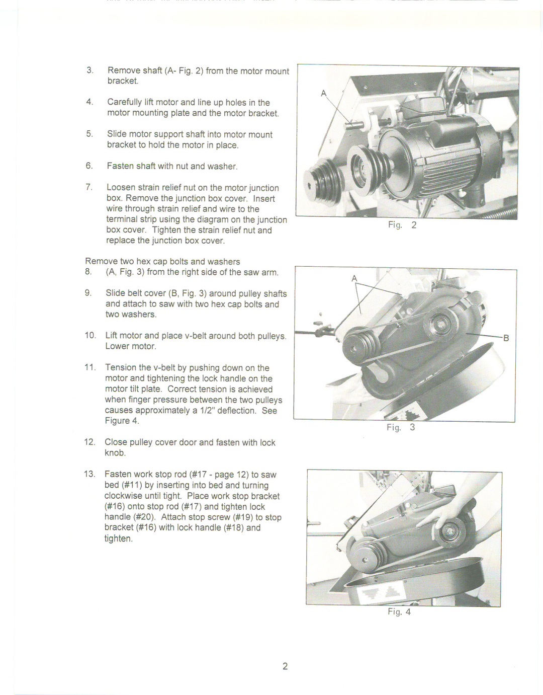
3.Remove shaft (A- Fig. 2) from the motor mount bracket.
4.Carefully lift motor and line up holes in the motor mounting plate and the motor bracket.
5.Slide motor support shaft into motor mount bracket to hold the motor in place.
6.Fasten shaft with nut and washer.
7.Loosen strain relief nut on the motor junction box. Remove the junction box cover. Insert wire through strain relief and wire to the terminal strip using the diagram on the junction box cover. Tighten the strain relief nut and replace the junction box cover.
Remove two hex cap bolts and washers
8.(A, Fig. 3) from the right side of the saw arm.
9.Slide belt cover (8, Fig. 3) around pulley shafts
and attach to saw with two hex cap bolts and two washers.
10.Lift motor and place
11.Tension the
12.Close pulley cover door and fasten with lock knob.
13.Fasten work stop rod (#17 - page 12) to saw bed (#11) by inserting into bed and turning clockwise until tight. Place work stop bracket (#16) onto stop rod (#17) and tighten lock handle (#20). Attach stop screw (#19) to stop bracket (#16) with lock handle (#18) and tighten.
Fig. 2
Fig. 3
Fig. 4
2