20

Servicing the hydraulic control cylinder

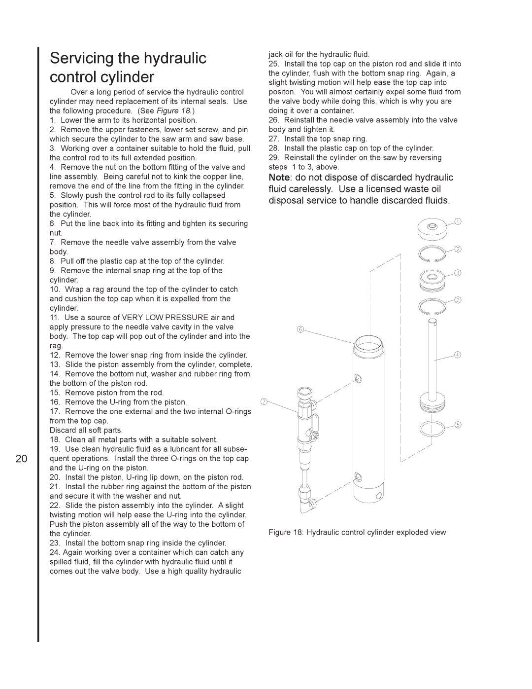
Over a long period of service the hydraulic control cylinder may need replacement of its internal seals. Use the following procedure. (See Figure 18.)

1.Lower the arm to its horizontal position.

2.Remove the upper fasteners, lower set screw, and pin which secure the cylinder to the saw arm and saw base.

3.Working over a container suitable to hold the fluid, pull the control rod to its full extended position.

4.Remove the nut on the bottom fitting of the valve and line assembly. Being careful not to kink the copper line, remove the end of the line from the fitting in the cylinder.

5.Slowly push the control rod to its fully collapsed position. This will force most of the hydraulic fluid from the cylinder.

6.Put the line back into its fitting and tighten its securing nut.

7.Remove the needle valve assembly from the valve body.

8.Pull off the plastic cap at the top of the cylinder.

9.Remove the internal snap ring at the top of the cylinder.

10.Wrap a rag around the top of the cylinder to catch and cushion the top cap when it is expelled from the cylinder.

11.Use a source of VERY LOW PRESSURE air and apply pressure to the needle valve cavity in the valve body. The top cap will pop out of the cylinder and into the rag.

12.Remove the lower snap ring from inside the cylinder.

13.Slide the piston assembly from the cylinder, complete.

14.Remove the bottom nut, washer and rubber ring from the bottom of the piston rod.

15.Remove piston from the rod.

16.Remove the U-ring from the piston.

17.Remove the one external and the two internal O-rings from the top cap.

Discard all soft parts.

18.Clean all metal parts with a suitable solvent.

19.Use clean hydraulic fluid as a lubricant for all subse- quent operations. Install the three O-rings on the top cap and the U-ring on the piston.

20.Install the piston, U-ring lip down, on the piston rod.

21.Install the rubber ring against the bottom of the piston and secure it with the washer and nut.

22.Slide the piston assembly into the cylinder. A slight twisting motion will help ease the U-ring into the cylinder. Push the piston assembly all of the way to the bottom of the cylinder.

23.Install the bottom snap ring inside the cylinder.

24.Again working over a container which can catch any spilled fluid, fill the cylinder with hydraulic fluid until it comes out the valve body. Use a high quality hydraulic

jack oil for the hydraulic fluid.

25.Install the top cap on the piston rod and slide it into the cylinder, flush with the bottom snap ring. Again, a slight twisting motion will help ease the top cap into positon. You will almost certainly expel some fluid from the valve body while doing this, which is why you are doing it over a container.

26.Reinstall the needle valve assembly into the valve body and tighten it.

27.Install the top snap ring.

28.Install the plastic cap on top of the cylinder.

29.Reinstall the cylinder on the saw by reversing steps 1 to 3, above.

Note: do not dispose of discarded hydraulic fluid carelessly. Use a licensed waste oil disposal service to handle discarded fluids.

Figure 18: Hydraulic control cylinder exploded view

Page 20
Image 20
Jet Tools J-3410-2 Servicing the hydraulic control cylinder, Hydraulic control cylinder exploded view

J-3410-2, J-3410 specifications

Jet Tools is renowned for its high-quality woodworking and metalworking equipment, and the J-3410 and J-3410-2 drill presses are prime examples of this commitment to excellence. These machines are engineered for precision, durability, and efficiency, appealing to both hobbyists and professional craftsmen.

The J-3410 features a robust 1 HP motor that provides ample power for a variety of drilling applications. This strength enables it to handle a wide range of materials, making it versatile enough for various projects. The machine operates at five different speeds, ranging from 600 to 3,100 RPM, allowing users to select the ideal speed for the specific material and drill bit size they are using. This versatility is crucial for achieving the desired results, whether it’s delicate woodwork or tougher metals.

One of the standout features of the J-3410 is its adjustable table, which can tilt up to 45 degrees, facilitating angled drilling. The table is constructed from heavy-duty cast iron, ensuring stability and reducing vibration, which is vital for precision work. Additionally, this model comes with a built-in laser guide that provides an accurate reference point for drilling, enhancing user efficiency and accuracy.

The J-3410-2 model builds upon the features of the J-3410, offering dual laser guides for even greater precision. These guides help users easily align the drill bit, ensuring that holes are drilled exactly where intended. The dual lasers also enhance visibility, especially in low-light environments. This model also includes a larger work table, allowing for drilling operations on bigger workpieces without compromising stability.

Both models are equipped with a heavy-duty, quick-adjust depth stop. This feature allows for consistency in repetitive drilling tasks, which is essential for users who need to achieve uniform results. They also feature an easy-to-use belt and pulley system for speed changes, ensuring that the transition between different speeds is effortless.

Safety is paramount in the design of the J-3410 and J-3410-2 press. A protective on/off switch prevents accidental start-ups, while the cast iron construction enhances overall stability and reduces the likelihood of accidents during operation.

The Jet Tools J-3410 and J-3410-2 combine power, precision, and safety, making them excellent choices for anyone in need of reliable drilling equipment. Whether for professional use or personal projects, these drill presses stand out in their class, showcasing Jet's commitment to quality and innovation.