14

Maintenance

Replacing blades

1.Disconnect the saw from its electrical power source to prevent accidental start-ups.

2.Raise the saw arm to its full vertical position and lock it in place using the quick shut off valve on the hydraulic control cylinder.

3.Lift the safety cover in the lower portion of the blade guard door by sliding it upward. There is no need to remove it completely from its slot.

4.Remove the two screws with plastic knobs which hold the blade guard door closed and swing the door open to expose the drive and idler wheels, and the blade.

5.Turn the blade tension handle counterclockwise until the blade hangs loose in the saw arm.

6.Use leather gloves to prevent cuts and scratches and use protective eyewear which meets ANSI Specification Z87.1. and pull the blade off of the drive wheels and out of the blade guides. Store the blade carefully before proceeding.

7.Slide the new blade into the blade guides -- then loop the blade over the upper and lower drive wheels.

Note: it is possible to install the blade backwards. The teeth on the blade should be pointing downward, toward the motor, at the time the blade is installed.

8.Push the blade so it is seated against the shoulders of the wheels. When it is seated against the shoulders...

9....turn the blade tension wheel clockwise to increase tension on the blade. Don't over-tension the blade. Tension it enough so it doesn't slip while cutting.

10.When you are satisfied that the saw is tensioned correctly, reconnect the saw to its electrical power source.

11.Check the tracking of the blade according to instructions in the section on Adjusting blade tracking, below.

12.Close the wheel guard door and secure it using the two plastic knobbed screws.

13.Slide the safety cover downward in its slot until it is fully closed.

14.The new blade is installed and ready for the Blade break-in procedures.

Adjusting blade tracking

If the blade is fully tensioned, release tension slightly before attempting to adjust the saw blade tracking. A badly worn or bent blade will be extremely difficult to track properly -- if it can be tracked successfully, at all. The track of the saw blade is adjusted using the track adjustment mechanism on the idler wheel. The track adjustment tilts the wheel to "steer" the blade on the wheels. Tracking adjustment is performed with the saw arm in vertical position, blade guard doors open and the saw running. Therefore, USE EXTREME CAUTION WHEN PERFORMING BLADE TRACKING CHECKS AND ADJUSTMENTS.

To adjust blade tracking:

1.Loosen the sliding plate draw block bolt slightly so the adjustment set screw will be able to move the draw block.

2.Turn the coolant pump switch OFF, if coolant is used.

3.Turn the saw ON.

4.Insert a 4mm hex wrench in the socket head track adjustment set screw.

5.Turn the track adjustment set screw so the blade starts to move away from the shoulder -- then immediately turn the screw the other direction so the blade stops -- then moves slowly toward the shoulder.

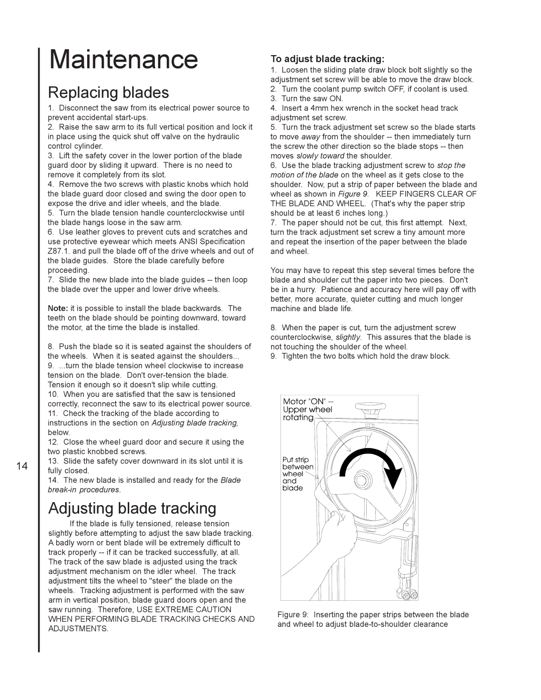
6.Use the blade tracking adjustment screw to stop the motion of the blade on the wheel as it gets close to the shoulder. Now, put a strip of paper between the blade and wheel as shown in Figure 9. KEEP FINGERS CLEAR OF THE BLADE AND WHEEL. (That's why the paper strip should be at least 6 inches long.)

7.The paper should not be cut, this first attempt. Next, turn the track adjustment set screw a tiny amount more and repeat the insertion of the paper between the blade and wheel.

You may have to repeat this step several times before the blade and shoulder cut the paper into two pieces. Don't be in a hurry. Patience and accuracy here will pay off with better, more accurate, quieter cutting and much longer machine and blade life.

8.When the paper is cut, turn the adjustment screw counterclockwise, slightly. This assures that the blade is not touching the shoulder of the wheel.

9.Tighten the two bolts which hold the draw block.

Figure 9: Inserting the paper strips between the blade and wheel to adjust blade-to-shoulder clearance

Page 14
Image 14
Jet Tools J-3410-2 operating instructions Replacing blades, Adjusting blade tracking, To adjust blade tracking

J-3410-2, J-3410 specifications

Jet Tools is renowned for its high-quality woodworking and metalworking equipment, and the J-3410 and J-3410-2 drill presses are prime examples of this commitment to excellence. These machines are engineered for precision, durability, and efficiency, appealing to both hobbyists and professional craftsmen.

The J-3410 features a robust 1 HP motor that provides ample power for a variety of drilling applications. This strength enables it to handle a wide range of materials, making it versatile enough for various projects. The machine operates at five different speeds, ranging from 600 to 3,100 RPM, allowing users to select the ideal speed for the specific material and drill bit size they are using. This versatility is crucial for achieving the desired results, whether it’s delicate woodwork or tougher metals.

One of the standout features of the J-3410 is its adjustable table, which can tilt up to 45 degrees, facilitating angled drilling. The table is constructed from heavy-duty cast iron, ensuring stability and reducing vibration, which is vital for precision work. Additionally, this model comes with a built-in laser guide that provides an accurate reference point for drilling, enhancing user efficiency and accuracy.

The J-3410-2 model builds upon the features of the J-3410, offering dual laser guides for even greater precision. These guides help users easily align the drill bit, ensuring that holes are drilled exactly where intended. The dual lasers also enhance visibility, especially in low-light environments. This model also includes a larger work table, allowing for drilling operations on bigger workpieces without compromising stability.

Both models are equipped with a heavy-duty, quick-adjust depth stop. This feature allows for consistency in repetitive drilling tasks, which is essential for users who need to achieve uniform results. They also feature an easy-to-use belt and pulley system for speed changes, ensuring that the transition between different speeds is effortless.

Safety is paramount in the design of the J-3410 and J-3410-2 press. A protective on/off switch prevents accidental start-ups, while the cast iron construction enhances overall stability and reduces the likelihood of accidents during operation.

The Jet Tools J-3410 and J-3410-2 combine power, precision, and safety, making them excellent choices for anyone in need of reliable drilling equipment. Whether for professional use or personal projects, these drill presses stand out in their class, showcasing Jet's commitment to quality and innovation.