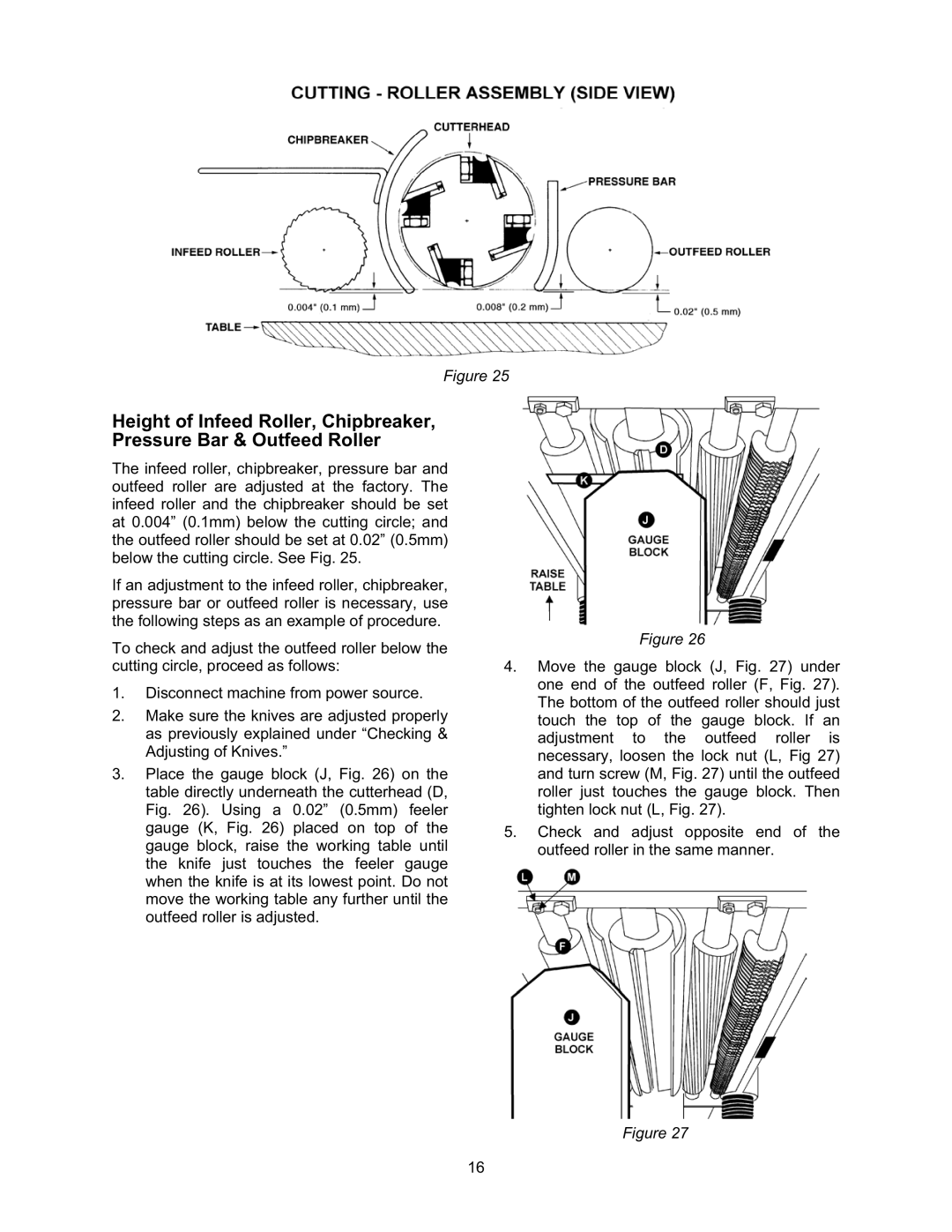
Figure 25
Height of Infeed Roller, Chipbreaker, Pressure Bar & Outfeed Roller
The infeed roller, chipbreaker, pressure bar and outfeed roller are adjusted at the factory. The infeed roller and the chipbreaker should be set at 0.004” (0.1mm) below the cutting circle; and the outfeed roller should be set at 0.02” (0.5mm) below the cutting circle. See Fig. 25.
If an adjustment to the infeed roller, chipbreaker, pressure bar or outfeed roller is necessary, use the following steps as an example of procedure.
To check and adjust the outfeed roller below the cutting circle, proceed as follows:
1.Disconnect machine from power source.
2.Make sure the knives are adjusted properly as previously explained under “Checking & Adjusting of Knives.”
3.Place the gauge block (J, Fig. 26) on the table directly underneath the cutterhead (D, Fig. 26). Using a 0.02” (0.5mm) feeler gauge (K, Fig. 26) placed on top of the gauge block, raise the working table until the knife just touches the feeler gauge when the knife is at its lowest point. Do not move the working table any further until the outfeed roller is adjusted.
Figure 26
4.Move the gauge block (J, Fig. 27) under one end of the outfeed roller (F, Fig. 27). The bottom of the outfeed roller should just touch the top of the gauge block. If an adjustment to the outfeed roller is necessary, loosen the lock nut (L, Fig 27) and turn screw (M, Fig. 27) until the outfeed roller just touches the gauge block. Then tighten lock nut (L, Fig. 27).
5.Check and adjust opposite end of the outfeed roller in the same manner.
Figure 27
16