Installing the Cooker Hood
Fitting the Wall Brackets
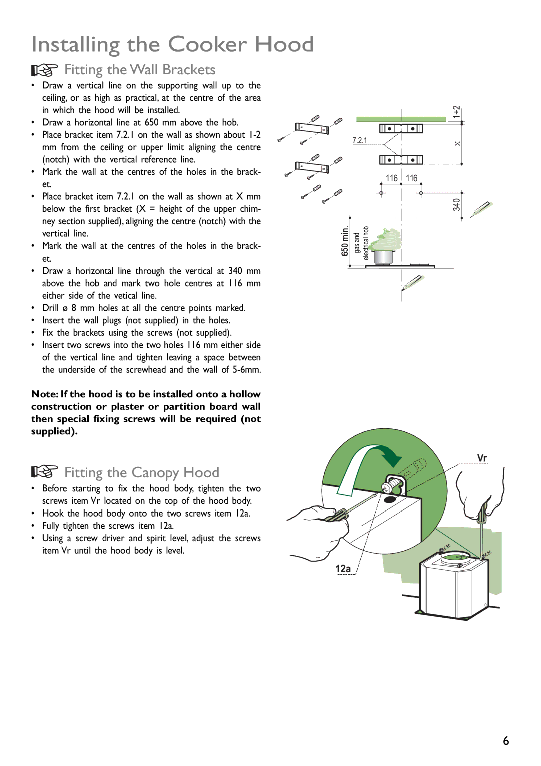
• Draw a vertical line on the supporting wall up to the ceiling, or as high as practical, at the centre of the area in which the hood will be installed.
• Draw a horizontal line at 650 mm above the hob.
• Place bracket item 7.2.1 on the wall as shown about
• Mark the wall at the centres of the holes in the brack- et.
• Place bracket item 7.2.1 on the wall as shown at X mm below the first bracket (X = height of the upper chim- ney section supplied), aligning the centre (notch) with the vertical line.
•Mark the wall at the centres of the holes in the brack- et.
•Draw a horizontal line through the vertical at 340 mm above the hob and mark two hole centres at 116 mm either side of the vetical line.
•Drill ø 8 mm holes at all the centre points marked.
•Insert the wall plugs (not supplied) in the holes.
•Fix the brackets using the screws (not supplied).
•Insert two screws into the two holes 116 mm either side of the vertical line and tighten leaving a space between the underside of the screwhead and the wall of
Note: If the hood is to be installed onto a hollow construction or plaster or partition board wall then special fixing screws will be required (not supplied).
Fitting the Canopy Hood
• Before starting to fix the hood body, tighten the two screws item Vr located on the top of the hood body.
•Hook the hood body onto the two screws item 12a.
•Fully tighten the screws item 12a.
•Using a screw driver and spirit level, adjust the screws item Vr until the hood body is level.
|
| 1÷2 |
| 7.2.1 | X |
|
| |
| 116 | 116 |
|
| 340 |
650 min. | gas and electrical hob |
|
Vr
12a
6
