364985-XIM-B-0508

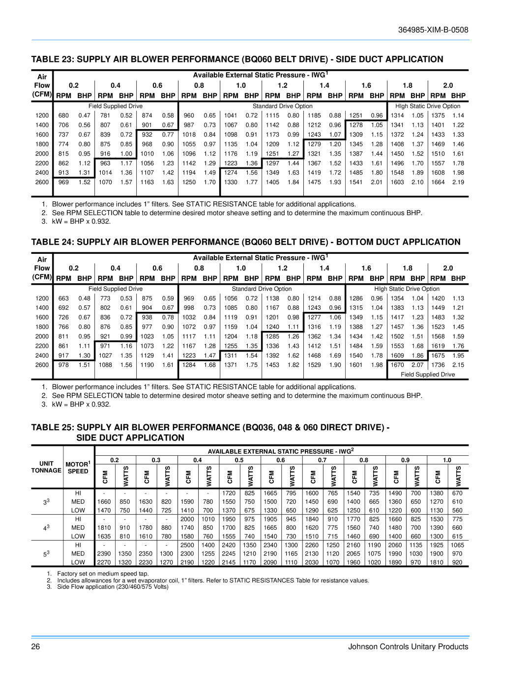
TABLE 23: SUPPLY AIR BLOWER PERFORMANCE (BQ060 BELT DRIVE) - SIDE DUCT APPLICATION

Air


Available External Static Pressure - IWG1


Flow

0.2

0.4

0.6

0.8

1.0

1.2

1.4


1.6


1.8

2.0

(CFM)

RPM

BHP

RPM

BHP

RPM

BHP

RPM

BHP

RPM

BHP

RPM

BHP

RPM BHP

RPM BHP

RPM BHP

RPM BHP


Field Supplied Drive


Standard Drive Option


HIgh Static Drive Option

1200

680

0.47

781

0.52

874

0.58

960

0.65

1041

0.72

1115

0.80

1185

0.88

1251

0.96

1314

1.05

1375

1.14

1400

706

0.56

807

0.61

901

0.67

987

0.73

1067

0.80

1142

0.88

1212

0.96

1278

1.05

1341

1.13

1401

1.22

1600

737

0.67

839

0.72

932

0.77

1018

0.84

1098

0.91

1173

0.99

1243

1.07

1309

1.15

1372

1.24

1433

1.33

1800

774

0.80

875

0.85

968

0.90

1055

0.97

1135

1.04

1209

1.12

1279

1.20

1345

1.28

1408

1.37

1469

1.46

2000

815

0.95

916

1.00

1010

1.06

1096

1.12

1176

1.19

1251

1.27

1321

1.35

1387

1.44

1450

1.52

1510

1.61

2200

862

1.12

963

1.17

1056

1.23

1142

1.29

1223

1.36

1297

1.44

1367

1.52

1433

1.61

1496

1.70

1557

1.78

2400

913

1.31

1014

1.36

1107

1.42

1194

1.49

1274

1.56

1349

1.63

1419

1.72

1485

1.80

1548

1.89

1608

1.98

2600

969

1.52

1070

1.57

1163

1.63

1250

1.70

1330

1.77

1405

1.84

1475

1.93

1541

2.01

1603

2.10

1664

2.19


1.Blower performance includes 1” filters. See STATIC RESISTANCE table for additional applications.

2.See RPM SELECTION table to determine desired motor sheave setting and to determine the maximum continuous BHP.

3.kW = BHP x 0.932.

TABLE 24: SUPPLY AIR BLOWER PERFORMANCE (BQ060 BELT DRIVE) - BOTTOM DUCT APPLICATION

Air


Available External Static Pressure - IWG1


Flow

0.2

0.4

0.6

0.8

1.0

1.2


1.4


1.6


1.8

2.0

(CFM)

RPM

BHP

RPM

BHP

RPM

BHP

RPM

BHP

RPM

BHP

RPM BHP

RPM BHP

RPM BHP

RPM BHP

RPM BHP


Field Supplied Drive


Standard Drive Option


HIgh Static Drive Option


1200

663

0.48

773

0.53

875

0.59

969

0.65

1056

0.72

1138

0.80

1214

0.88

1286

0.96

1354

1.04

1420

1.13

1400

692

0.57

802

0.61

904

0.67

998

0.73

1085

0.80

1167

0.88

1243

0.96

1315

1.04

1383

1.13

1449

1.21

1600

726

0.67

836

0.72

938

0.78

1032

0.84

1119

0.91

1201

0.98

1277

1.06

1349

1.15

1417

1.23

1483

1.32

1800

766

0.80

876

0.85

977

0.90

1072

0.97

1159

1.04

1240

1.11

1316

1.19

1388

1.27

1457

1.36

1523

1.45

2000

811

0.95

921

0.99

1023

1.05

1117

1.11

1204

1.18

1285

1.26

1362

1.34

1434

1.42

1502

1.51

1568

1.59

2200

861

1.11

971

1.16

1073

1.22

1167

1.28

1255

1.35

1336

1.43

1412

1.51

1484

1.59

1553

1.68

1619

1.76

2400

917

1.30

1027

1.35

1129

1.41

1223

1.47

1311

1.54

1392

1.62

1468

1.69

1540

1.78

1609

1.86

1675

1.95

2600

978

1.51

1088

1.56

1190

1.61

1284

1.68

1371

1.75

1453

1.82

1529

1.90

1601

1.98

1670

2.07

1736

2.15


Field Supplied Drive

1.Blower performance includes 1” filters. See STATIC RESISTANCE table for additional applications.

2.See RPM SELECTION table to determine desired motor sheave setting and to determine the maximum continuous BHP.

3.kW = BHP x 0.932.

TABLE 25: SUPPLY AIR BLOWER PERFORMANCE (BQ036, 048 & 060 DIRECT DRIVE) -

SIDE DUCT APPLICATION


AVAILABLE EXTERNAL STATIC PRESSURE - IWG2


UNIT

MOTOR1

0.2

0.3

0.4

0.5

0.6

0.7

0.8

0.9

1.0

TONNAGE

SPEED

CFM

WATTS

CFM

WATTS

CFM

WATTS

CFM

WATTS

CFM

WATTS

CFM

WATTS

CFM

WATTS

CFM

WATTS

CFM

WATTS


HI

-

-

-

-

-

-

1720

825

1665

795

1600

765

1540

735

1490

700

1380

670

33

MED

1660

850

1630

820

1590

780

1550

750

1500

720

1450

690

1400

665

1360

650

1270

610


LOW

1470

750

1440

725

1410

700

1370

675

1330

650

1290

625

1250

610

1220

600

1130

560


HI

-

-

-

-

2000

1010

1950

975

1905

945

1840

910

1770

825

1660

825

1530

775

43

MED

1810

910

1780

880

1740

850

1700

825

1665

800

1620

775

1560

740

1480

700

1390

660


LOW

1635

810

1610

780

1580

760

1555

740

1540

730

1510

715

1460

690

1400

660

1300

615


HI

-

-

-

-

2500

1400

2420

1350

2340

1300

2260

1250

2160

1190

2060

1135

1925

1065

53

MED

2390

1350

2350

1300

2300

1255

2245

1210

2190

1165

2130

1120

2065

1075

1990

1030

1900

970


LOW

2270

1320

2230

1270

2190

1220

2145

1170

2090

1110

2030

1070

1960

1020

1890

970

1810

920

1.Factory set on medium speed tap.

2.Includes allowances for a wet evaporator coil, 1” filters. Refer to STATIC RESISTANCES Table for resistance values.

3.Side Flow application (230/460/575 Volts)

26

Johnson Controls Unitary Products

Page 26
Image 26
Johnson Controls BQ 048, BQ 060, BQ 036 installation manual Bhp Rpm Bhp

BQ 048, BQ 036, BQ 060 specifications

Johnson Controls has established itself as a leading player in the HVAC and building management industries, and its BQ series of chillers - including the BQ 060, BQ 036, and BQ 048 - reflects this commitment to innovation and efficiency. These models are designed to provide advanced cooling solutions suitable for a variety of commercial applications.

The BQ 060 is particularly notable for its high-performance capabilities. With a cooling capacity of 60 tons, it utilizes variable-speed compressors, allowing it to adjust its performance based on the cooling demand. This flexibility not only enhances energy efficiency but also reduces operational costs. The unit incorporates advanced microprocessor controls that facilitate seamless integration with building management systems, enabling real-time monitoring and adjustments.

Moving on to the BQ 036, this model is engineered for facilities that require a smaller footprint but still demand reliability and efficiency. With a cooling capacity of 36 tons, it features a compact design without compromising on performance. The BQ 036 also employs environmentally friendly refrigerants, aligning with Johnson Controls' commitment to sustainability. Enhanced insulation and sound-dampening technologies make it an ideal choice for noise-sensitive environments, ensuring comfort without sacrificing efficiency.

The BQ 048 lies in between the two, with a capacity of 48 tons, making it versatile for medium-sized commercial buildings. Its design incorporates a modular approach, allowing for easy scalability in future expansions. This model also features energy recovery options that can utilize excess heat to improve overall efficiency, further solidifying its role in sustainable building practices. Its user-friendly interface enhances operability, simplifying management for building operators.

All three models of the BQ series share key characteristics, such as robust construction to withstand diverse environmental conditions, and low maintenance requirements thanks to their durable components. They utilize advanced technologies for temperature control and energy efficiency, including an intelligent controller that automates more routine tasks. Together, the BQ 060, BQ 036, and BQ 048 offer comprehensive solutions that cater to the growing demands of energy efficiency, sustainability, and reliability in modern building operations. With these chillers, Johnson Controls continues to lead the way in shaping the future of HVAC solutions.