364985-XIM-B-0508

The UCB will flash the last five alarms on the LED. If the compressor is locked out, cancel any call for cool- ing. This will reset any compressor lock outs.

NOTE: While the above step will reset any lockouts, the compressor may be held off for the ASCD. See the next step.

10.If 24 volts is present at the UCB Y1 terminal and none of the switches are open and the compressor is not locked out, the UCB may have the compres- sor in an ASCD. Check the LED for an indication of an ASCD cycle. The ASCD should time out within 5 minutes. Press and release the TEST button to reset all ASCDs.

11.If 24 volts is present at the UCB Y1 terminal and the compressor is not out due to a protective switch trip, repeat trip lock out, or ASCD, the economizer termi- nals of the UCB may be improperly wired. Check for 24 volts at the Y1 “OUT” terminal of the UCB. If 24 volts is present, trace the wiring from Y1 “OUT” for incorrect wiring. If 24 volts is not present at the Y1 “OUT” terminal, the UCB must be replaced.

12.For units without economizers: If 24 volts is present at the Y1 OUT terminal, check for 24 volts at the Y1 “ECON” terminal. If 24 volts is not present, check for loose wiring from the Y1 “OUT” terminal to the Mate-N-Lock plug, the jumper in the Mate-N- Lock plug, and in the wiring from the Mate-N-Lock plug to the Y1 “ECON” terminal.

13.For units with economizers: If 24 volts is present at the Y1 “OUT” terminal, check for 24 volts at the Y1 “ECON” terminal. If 24 volts is not present, check for loose wiring from the Y1 “OUT” terminal to the Mate-N-Lock plug, a poor connection between the UCB and economizer Mate-N-Lock plugs, loose wiring from the Mate-N-Lock plug to the econo- mizer, back to the Mate-N-Lock plug, and from the Mate-N-Lock plug to the Y1 “ECON” terminal. If nothing is found, the economizer actuator may have faulted and is failing to return the 24-volt “call” to the Y1 “ECON” terminal even though the econo- mizer is not providing free cooling. To test, discon- nect the Mate-N-Locks and jumper between the WHITE and YELLOW wires of the UCB’s Mate-N- Lock plug. If the compressor energizes, there is a fault in the economizer wiring or actuator.

14.The UCB can be programmed to lock out compres- sor operation during free cooling and in low ambi- ent conditions. These options are not enabled by default. Local distributors can test the UCB for this programming.

For units with factory installed economizers, the UCB is programmed to lock out compressor opera- tion when the LAS set point is reached.

For units without factory installed or with field installed economizers, the UCB allows compressor operation all the time. This programming can be checked or changed by the local distributor.

15.If none of the above correct the error, replace the UCB.

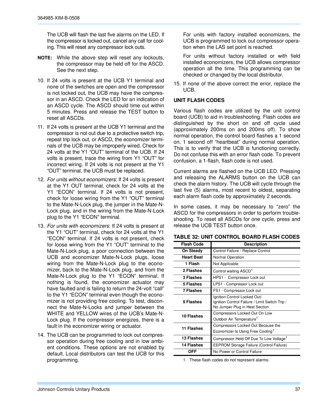
UNIT FLASH CODES

Various flash codes are utilized by the unit control board (UCB) to aid in troubleshooting. Flash codes are distinguished by the short on and off cycle used (approximately 200ms on and 200ms off). To show normal operation, the control board flashes a 1 second on, 1 second off “heartbeat” during normal operation. This is to verify that the UCB is functioning correctly. Do not confuse this with an error flash code. To prevent confusion, a 1-flash, flash code is not used.

Current alarms are flashed on the UCB LED. Pressing and releasing the ALARMS button on the UCB can check the alarm history. The UCB will cycle through the last five (5) alarms, most recent to oldest, separating each alarm flash code by approximately 2 seconds.

In some cases, it may be necessary to “zero” the ASCD for the compressors in order to perform trouble- shooting. To reset all ASCDs for one cycle, press and release the UCB TEST button once.

TABLE 32: UNIT CONTROL BOARD FLASH CODES

Flash Code

Description

On Steady

Control Failure - Replace Control

Heart Beat

Normal Operation

1 Flash

Not Applicable

2 Flashes

Control waiting ASCD1

3 Flashes

HPS1 - Compressor Lock out

5 Flashes

LPS1 - Compressor Lock out

7 Flashes

FS1 - Compressor Lock out

9 Flashes

Ignition Control Locked Out/

Ignition Control Failure / Limit Switch Trip /


No Jumper Plug in Heat Section


10 Flashes

Compressors Locked Out On Low

Outdoor Air Temperature1


11 Flashes

Compressors Locked Out Because the

Economizer Is Using Free Cooling1


13 Flashes

Compressor Held Off Due To Low Voltage1

14 Flashes

EEPROM Storage Failure (Control Failure)

OFF

No Power or Control Failure

1. These flash codes do not represent alarms.

Johnson Controls Unitary Products

37

Page 37
Image 37
Johnson Controls BQ 036, BQ 060, BQ 048 installation manual Unit Flash Codes, Unit Control Board Flash Codes

BQ 048, BQ 036, BQ 060 specifications

Johnson Controls has established itself as a leading player in the HVAC and building management industries, and its BQ series of chillers - including the BQ 060, BQ 036, and BQ 048 - reflects this commitment to innovation and efficiency. These models are designed to provide advanced cooling solutions suitable for a variety of commercial applications.

The BQ 060 is particularly notable for its high-performance capabilities. With a cooling capacity of 60 tons, it utilizes variable-speed compressors, allowing it to adjust its performance based on the cooling demand. This flexibility not only enhances energy efficiency but also reduces operational costs. The unit incorporates advanced microprocessor controls that facilitate seamless integration with building management systems, enabling real-time monitoring and adjustments.

Moving on to the BQ 036, this model is engineered for facilities that require a smaller footprint but still demand reliability and efficiency. With a cooling capacity of 36 tons, it features a compact design without compromising on performance. The BQ 036 also employs environmentally friendly refrigerants, aligning with Johnson Controls' commitment to sustainability. Enhanced insulation and sound-dampening technologies make it an ideal choice for noise-sensitive environments, ensuring comfort without sacrificing efficiency.

The BQ 048 lies in between the two, with a capacity of 48 tons, making it versatile for medium-sized commercial buildings. Its design incorporates a modular approach, allowing for easy scalability in future expansions. This model also features energy recovery options that can utilize excess heat to improve overall efficiency, further solidifying its role in sustainable building practices. Its user-friendly interface enhances operability, simplifying management for building operators.

All three models of the BQ series share key characteristics, such as robust construction to withstand diverse environmental conditions, and low maintenance requirements thanks to their durable components. They utilize advanced technologies for temperature control and energy efficiency, including an intelligent controller that automates more routine tasks. Together, the BQ 060, BQ 036, and BQ 048 offer comprehensive solutions that cater to the growing demands of energy efficiency, sustainability, and reliability in modern building operations. With these chillers, Johnson Controls continues to lead the way in shaping the future of HVAC solutions.