PHASING

Check for proper compressor rotation. If the blower or compressors rotate in the wrong direction at start-up, the electrical connection to the unit is misphased. Change the incoming line connection phasing to obtain proper rotation. (Scroll compressors operate in only one direction. If the scroll is drawing low amperage, has similar suction and discharge pressures, or pro- ducing a high noise level, the scroll is misphased).

Scroll compressors require proper rotation to operate correctly. Do not change the internal wiring to make the blower, condenser fans, or compressor rotate correctly. Change the incoming power to the main terminal block to obtain proper rotation.

SUPPLY AIR BLOWERS

These blowers have either 3-speed direct drive motors, or single speed motors equipped with a belt drive. Belt drive units have a variable pitch motor pulley that allows the blower speed to be adjusted.

CHECKING SUPPLY AIR CFM

The RPM of the supply air blower will depend on the required CFM, the unit accessories or options and the static resistances of both the supply and the return air duct systems. With this information, the motor speed tap (direct drive) or the motor pulley number of turns open (belt drive) can be determined from the Blower Performance Data Tables.

Note the following:

1.The supply air CFM must be within the limitations shown in the Unit Application Data Table 1.

2.Pulleys can be adjusted in half turn increments.

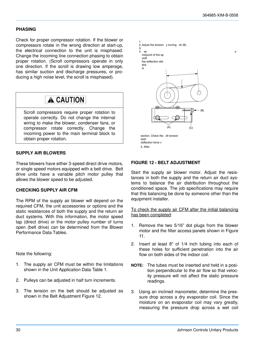
3.The tension on the belt should be adjusted as shown in the Belt Adjustment Figure 12.

PROCEDUREFORADJUSTINGBELTTENSION:364985-XIM-B-0508

1

Loosennu

(A)(topandbottom).


2

Adjustthet


byturningbolt(B).


3

Neverloosennuts(C)fromeachother.


4.Usebelttensioncheckertoapplyaperpendicularforcetobeonebeltatthe


midpointofthespanasshown.Thedeflectionforceshouldbeapplied


untilaspecificdeflectiondistanceof4mm(5/32")is

.Todetermine


thedeflection

fromnormalposition,useastraight

dgefrom


sheavetosheavedistanascereferenceline.herecommendedobtainedflectionforce


isasfollows:


DEFLFORCE


(A) (C)**Never(B)Loosen Tnsionnewbeltsatthemax.deflectionbetweenforcerecomendminandeforthebelt sdeflectionoperati.Check.forceAnyrethevalues-tenioningbelt.tensionshouldatleastfalltwotimestheduring.thfirstmax24.hoursof

5.Afteradjusting,re-tightennuts(A).

FIGURE 12 - BELT ADJUSTMENT

Start the supply air blower motor. Adjust the resis- tances in both the supply and the return air duct sys- tems to balance the air distribution throughout the conditioned space. The job specifications may require that this balancing be done by someone other than the equipment installer.

To check the supply air CFM after the initial balancing has been completed:

1.Remove the two 5/16” dot plugs from the blower motor and the filter access panels shown in Figure 11.

2.Insert at least 8" of 1/4 inch tubing into each of these holes for sufficient penetration into the air flow on both sides of the indoor coil.

NOTE: The tubes must be inserted and held in a posi- tion perpendicular to the air flow so that veloc- ity pressure will not affect the static pressure readings.

3.Using an inclined manometer, determine the pres- sure drop across a dry evaporator coil. Since the moisture on an evaporator coil may vary greatly, measuring the pressure drop across a wet coil

30

Johnson Controls Unitary Products

Page 30
Image 30
Johnson Controls BQ 060, BQ 036, BQ 048 installation manual Phasing, Supply AIR Blowers, Checking Supply AIR CFM

BQ 048, BQ 036, BQ 060 specifications

Johnson Controls has established itself as a leading player in the HVAC and building management industries, and its BQ series of chillers - including the BQ 060, BQ 036, and BQ 048 - reflects this commitment to innovation and efficiency. These models are designed to provide advanced cooling solutions suitable for a variety of commercial applications.

The BQ 060 is particularly notable for its high-performance capabilities. With a cooling capacity of 60 tons, it utilizes variable-speed compressors, allowing it to adjust its performance based on the cooling demand. This flexibility not only enhances energy efficiency but also reduces operational costs. The unit incorporates advanced microprocessor controls that facilitate seamless integration with building management systems, enabling real-time monitoring and adjustments.

Moving on to the BQ 036, this model is engineered for facilities that require a smaller footprint but still demand reliability and efficiency. With a cooling capacity of 36 tons, it features a compact design without compromising on performance. The BQ 036 also employs environmentally friendly refrigerants, aligning with Johnson Controls' commitment to sustainability. Enhanced insulation and sound-dampening technologies make it an ideal choice for noise-sensitive environments, ensuring comfort without sacrificing efficiency.

The BQ 048 lies in between the two, with a capacity of 48 tons, making it versatile for medium-sized commercial buildings. Its design incorporates a modular approach, allowing for easy scalability in future expansions. This model also features energy recovery options that can utilize excess heat to improve overall efficiency, further solidifying its role in sustainable building practices. Its user-friendly interface enhances operability, simplifying management for building operators.

All three models of the BQ series share key characteristics, such as robust construction to withstand diverse environmental conditions, and low maintenance requirements thanks to their durable components. They utilize advanced technologies for temperature control and energy efficiency, including an intelligent controller that automates more routine tasks. Together, the BQ 060, BQ 036, and BQ 048 offer comprehensive solutions that cater to the growing demands of energy efficiency, sustainability, and reliability in modern building operations. With these chillers, Johnson Controls continues to lead the way in shaping the future of HVAC solutions.