Johnson Controls IFC-640 Placement of Equipment Chassis and Cabinet, Configuration Guidelines

Models: IFC-640

1 9
Download 9 pages 51.15 Kb
Page 5
Image 5

Placement of Equipment

in Chassis and Cabinet

The following guidelines outline the IFC-640’s flexible system design.

Rows: The first row of equipment in the cabinet mounts in chassis CHS-M2. Mount the second, third, or fourth rows of equipment in chassis CHS-4MB(see IFC-640 Installation Man- ual regarding panel output modules) or CHS-4L(for voice com- ponents, see Voice Alarm System Manual).

Wiring: When designing the cabinet layout, consider separa- tion of power-limited and non-power-limited wiring as discussed in the IFC-640 Installation Manual.

Positions: A chassis offers four basic side-by-side positions for components; the number of modules that can be mounted in each position depends on the chassis model and the size of the individual module. There are a variety of standoffs and hardware items available for different combinations and configurations of components.

It is critical that all mounting holes of the IFC-640 are secured with a screw or standoff to ensure continuity of Earth Ground.

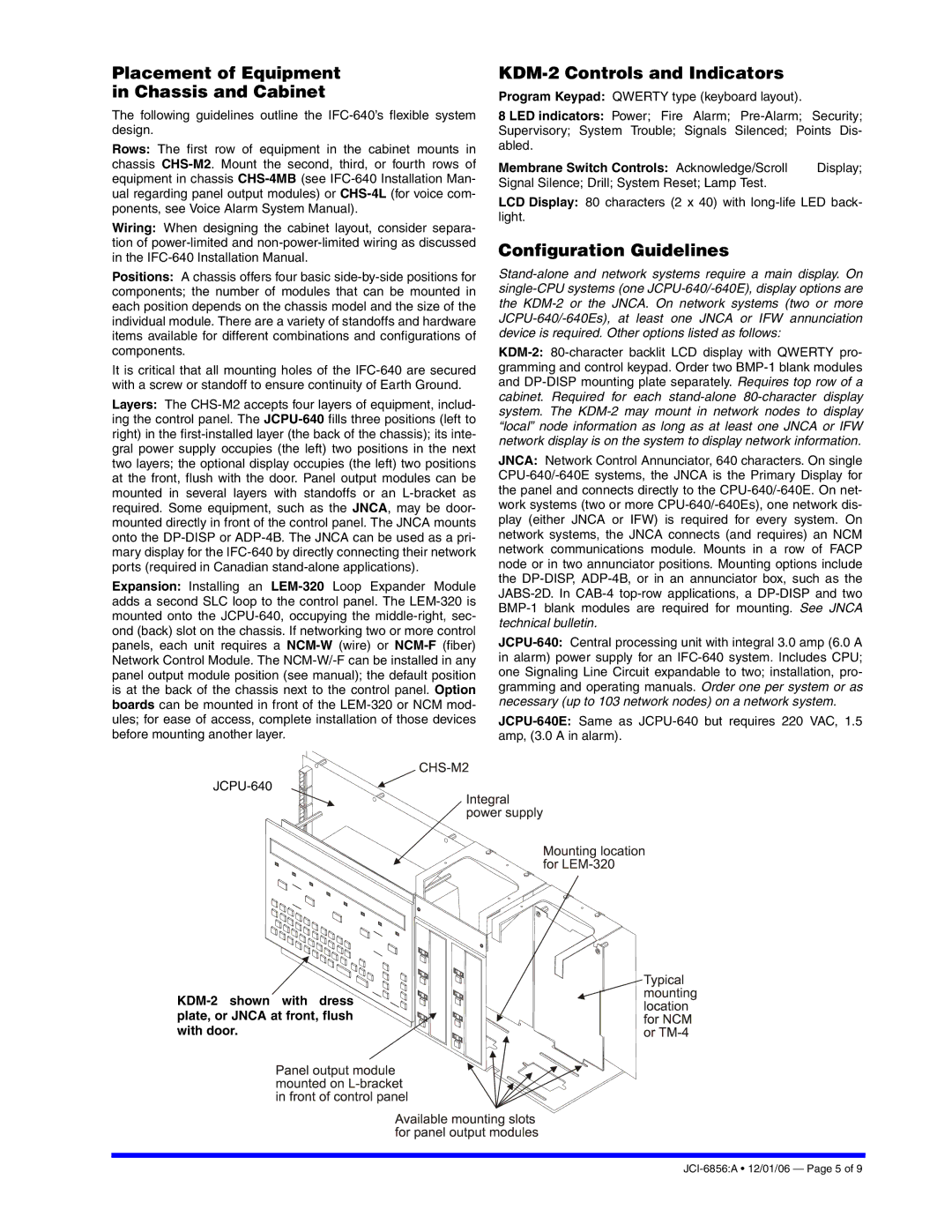
Layers: The CHS-M2 accepts four layers of equipment, includ- ing the control panel. The JCPU-640fills three positions (left to right) in the first-installed layer (the back of the chassis); its inte- gral power supply occupies (the left) two positions in the next two layers; the optional display occupies (the left) two positions at the front, flush with the door. Panel output modules can be mounted in several layers with standoffs or an L-bracket as required. Some equipment, such as the JNCA, may be door- mounted directly in front of the control panel. The JNCA mounts onto the DP-DISP or ADP-4B. The JNCA can be used as a pri- mary display for the IFC-640 by directly connecting their network ports (required in Canadian stand-alone applications).

Expansion: Installing an LEM-320Loop Expander Module adds a second SLC loop to the control panel. The LEM-320 is mounted onto the JCPU-640, occupying the middle-right, sec- ond (back) slot on the chassis. If networking two or more control panels, each unit requires a NCM-W(wire) or NCM-F(fiber) Network Control Module. The NCM-W/-F can be installed in any panel output module position (see manual); the default position is at the back of the chassis next to the control panel. Option boards can be mounted in front of the LEM-320 or NCM mod- ules; for ease of access, complete installation of those devices before mounting another layer.

JCPU-640

KDM-2 shown with dress plate, or JNCAatfront, flush with door.

KDM-2 Controls and Indicators

Program Keypad: QWERTY type (keyboard layout).


8 LED indicators: Power; Fire Alarm; Pre-Alarm;

Security;

Supervisory; System Trouble; Signals Silenced; Points Dis-

abled.


Membrane Switch Controls: Acknowledge/Scroll

Display;

Signal Silence; Drill; System Reset; Lamp Test.


LCD Display: 80 characters (2 x 40) with long-life LED back- light.

Configuration Guidelines

Stand-alone and network systems require a main display. On single-CPU systems (one JCPU-640/-640E), display options are the KDM-2 or the JNCA. On network systems (two or more JCPU-640/-640Es), at least one JNCA or IFW annunciation device is required. Other options listed as follows:

KDM-2:80-character backlit LCD display with QWERTY pro- gramming and control keypad. Order two BMP-1 blank modules and DP-DISP mounting plate separately. Requires top row of a cabinet. Required for each stand-alone80-character display system. The KDM-2 may mount in network nodes to display “local” node information as long as at least one JNCA or IFW network display is on the system to display network information.

JNCA: Network Control Annunciator, 640 characters. On single CPU-640/-640E systems, the JNCA is the Primary Display for the panel and connects directly to the CPU-640/-640E. On net- work systems (two or more CPU-640/-640Es), one network dis- play (either JNCA or IFW) is required for every system. On network systems, the JNCA connects (and requires) an NCM network communications module. Mounts in a row of FACP node or in two annunciator positions. Mounting options include the DP-DISP, ADP-4B, or in an annunciator box, such as the JABS-2D. In CAB-4 top-row applications, a DP-DISP and two BMP-1 blank modules are required for mounting. See JNCA technical bulletin.

JCPU-640:Central processing unit with integral 3.0 amp (6.0 A in alarm) power supply for an IFC-640 system. Includes CPU; one Signaling Line Circuit expandable to two; installation, pro- gramming and operating manuals. Order one per system or as necessary (up to 103 network nodes) on a network system.

JCPU-640E:Same as JCPU-640 but requires 220 VAC, 1.5 amp, (3.0 A in alarm).

JCI-6856:A • 12/01/06 — Page 5 of 9

Page 5
Image 5
Johnson Controls IFC-640 manual Placement of Equipment Chassis and Cabinet, KDM-2 Controls and Indicators

IFC-640 specifications

Johnson Controls IFC-640 is a pioneering fire alarm control panel that integrates advanced technologies to ensure safety and protection in commercial and industrial applications. As a part of the Johnson Controls extensive portfolio, the IFC-640 offers detailed monitoring and control capabilities, making it a reliable choice for fire management systems.

One of the standout features of the IFC-640 is its robust addressable technology. This system allows for precise identification of each alarm device, enabling quick location tracking during emergencies. The incorporation of intelligent algorithms enhances the panel's ability to distinguish between actual fire events and false alarms, thereby improving overall response efficiency.

Another significant characteristic of the IFC-640 is its user-friendly interface. The panel is equipped with a color LCD display that provides real-time status updates on the system’s operation. This visual clarity ensures that operators can quickly comprehend alerts and other vital information. The intuitive navigation allows users to manage settings and view system events with ease, minimizing the training required for new personnel.

The IFC-640 also boasts a modular architecture, allowing for seamless scalability. This feature enables the system to adapt to varying building sizes and complexities without needing extensive upgrades. Integration capabilities with third-party systems facilitate compatibility with existing infrastructure, making the IFC-640 a versatile choice for a diverse range of environments.

Network capabilities are enhanced with the panel's ability to connect monitoring stations and multiple units in a single system. This networking function allows for centralized management of multiple installations, improving overall safety management across large campuses or facilities.

Safety and reliability are further reinforced by the IFC-640’s built-in redundancy features. This ensures continuous operation even in the event of a power outage, providing peace of mind to facility managers and stakeholders.

In summary, the Johnson Controls IFC-640 fire alarm control panel exemplifies cutting-edge engineering with its addressable technology, user-friendly interface, modular design, and robust networking capabilities. With these features, it stands as an effective solution for safeguarding lives and property against fire hazards.