505309-UIM-D-0511

ADJUSTMENT OF MANIFOLD GAS PRESSURE & INPUT RATE

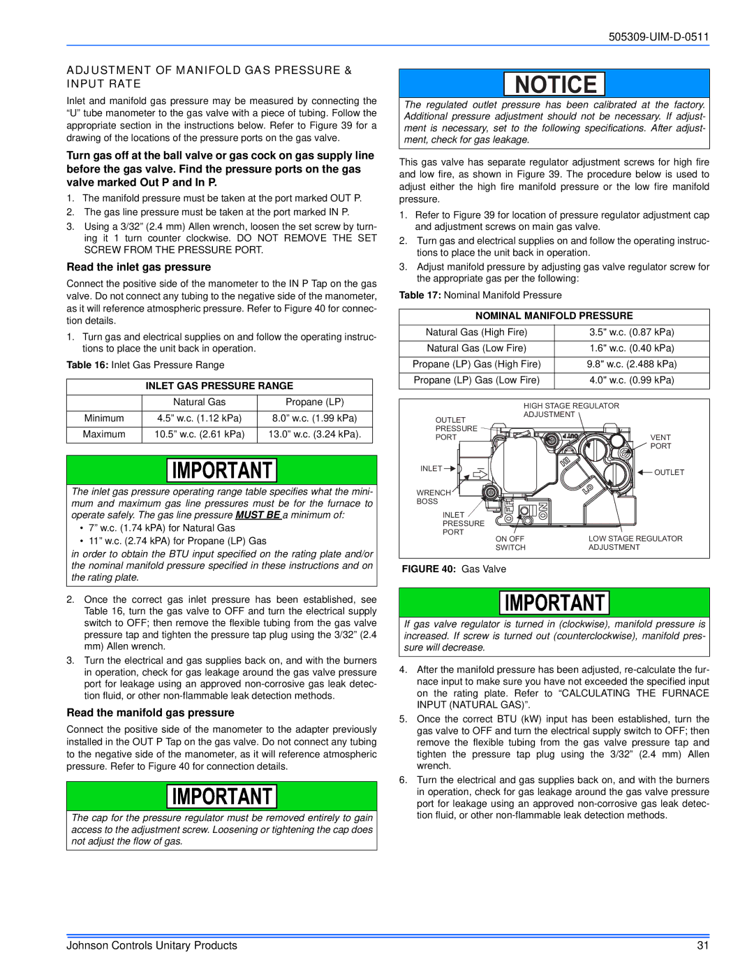
Inlet and manifold gas pressure may be measured by connecting the “U” tube manometer to the gas valve with a piece of tubing. Follow the appropriate section in the instructions below. Refer to Figure 39 for a drawing of the locations of the pressure ports on the gas valve.

Turn gas off at the ball valve or gas cock on gas supply line before the gas valve. Find the pressure ports on the gas valve marked Out P and In P.

1.The manifold pressure must be taken at the port marked OUT P.

2.The gas line pressure must be taken at the port marked IN P.

3.Using a 3/32” (2.4 mm) Allen wrench, loosen the set screw by turn- ing it 1 turn counter clockwise. DO NOT REMOVE THE SET SCREW FROM THE PRESSURE PORT.

Read the inlet gas pressure

Connect the positive side of the manometer to the IN P Tap on the gas valve. Do not connect any tubing to the negative side of the manometer, as it will reference atmospheric pressure. Refer to Figure 40 for connec- tion details.

1.Turn gas and electrical supplies on and follow the operating instruc- tions to place the unit back in operation.

Table 16: Inlet Gas Pressure Range

INLET GAS PRESSURE RANGE


Natural Gas


Propane (LP)


Minimum

4.5” w.c. (1.12 kPa)

8.0” w.c. (1.99 kPa)


Maximum

10.5” w.c. (2.61 kPa)

13.0” w.c. (3.24 kPa).


The inlet gas pressure operating range table specifies what the mini- mum and maximum gas line pressures must be for the furnace to operate safely. The gas line pressure MUST BE a minimum of:

7” w.c. (1.74 kPA) for Natural Gas

11” w.c. (2.74 kPA) for Propane (LP) Gas

in order to obtain the BTU input specified on the rating plate and/or the nominal manifold pressure specified in these instructions and on the rating plate.

2.Once the correct gas inlet pressure has been established, see Table 16, turn the gas valve to OFF and turn the electrical supply switch to OFF; then remove the flexible tubing from the gas valve pressure tap and tighten the pressure tap plug using the 3/32” (2.4 mm) Allen wrench.

3.Turn the electrical and gas supplies back on, and with the burners in operation, check for gas leakage around the gas valve pressure port for leakage using an approved non-corrosive gas leak detec- tion fluid, or other non-flammable leak detection methods.

Read the manifold gas pressure

Connect the positive side of the manometer to the adapter previously installed in the OUT P Tap on the gas valve. Do not connect any tubing to the negative side of the manometer, as it will reference atmospheric pressure. Refer to Figure 40 for connection details.

The cap for the pressure regulator must be removed entirely to gain access to the adjustment screw. Loosening or tightening the cap does not adjust the flow of gas.

NOTICE

The regulated outlet pressure has been calibrated at the factory. Additional pressure adjustment should not be necessary. If adjust- ment is necessary, set to the following specifications. After adjust- ment, check for gas leakage.

This gas valve has separate regulator adjustment screws for high fire and low fire, as shown in Figure 39. The procedure below is used to adjust either the high fire manifold pressure or the low fire manifold pressure.

1.Refer to Figure 39 for location of pressure regulator adjustment cap and adjustment screws on main gas valve.

2.Turn gas and electrical supplies on and follow the operating instruc- tions to place the unit back in operation.

3.Adjust manifold pressure by adjusting gas valve regulator screw for the appropriate gas per the following:

Table 17: Nominal Manifold Pressure

NOMINAL MANIFOLD PRESSURE

Natural Gas (High Fire)

3.5" w.c. (0.87 kPa)


Natural Gas (Low Fire)

1.6" w.c. (0.40 kPa)


Propane (LP) Gas (High Fire)

9.8" w.c. (2.488 kPa)


Propane (LP) Gas (Low Fire)

4.0" w.c. (0.99 kPa)


HIGH STAGE REGULATOR

ADJUSTMENT


OUTLET


PRESSURE


PORT

VENT


PORT

INLET

OUTLET


WRENCH


BOSS


INLET


PRESSURE


PORT

LOW STAGE REGULATOR

ON OFF

SWITCH

ADJUSTMENT

FIGURE 40: Gas Valve

If gas valve regulator is turned in (clockwise), manifold pressure is increased. If screw is turned out (counterclockwise), manifold pres- sure will decrease.

4.After the manifold pressure has been adjusted, re-calculate the fur- nace input to make sure you have not exceeded the specified input on the rating plate. Refer to “CALCULATING THE FURNACE INPUT (NATURAL GAS)”.

5.Once the correct BTU (kW) input has been established, turn the gas valve to OFF and turn the electrical supply switch to OFF; then remove the flexible tubing from the gas valve pressure tap and tighten the pressure tap plug using the 3/32” (2.4 mm) Allen wrench.

6.Turn the electrical and gas supplies back on, and with the burners in operation, check for gas leakage around the gas valve pressure port for leakage using an approved non-corrosive gas leak detec- tion fluid, or other non-flammable leak detection methods.

Johnson Controls Unitary Products

31

Page 31
Image 31
Johnson Controls TM9T*MP installation manual Adjustment of Manifold GAS Pressure & Input Rate, Read the inlet gas pressure

TM9T*MP specifications

Johnson Controls TM9T*MP is a state-of-the-art HVAC unit designed for modern commercial and residential applications. With its innovative technology and robust features, the TM9T*MP offers exceptional performance, efficiency, and reliability. This unit is engineered to provide optimal climate control, ensuring that indoor environments remain comfortable regardless of external weather conditions.

One of the main features of the TM9T*MP is its variable-speed compressor, which allows for precise temperature regulation and energy-efficient operation. This technology enables the unit to adjust its output based on the current demand, significantly reducing energy consumption compared to traditional systems. By operating at lower speeds during mild weather, the TM9T*MP minimizes energy costs while maintaining user comfort.

Another significant aspect of the TM9T*MP is its advanced multi-stage filtration system. This system includes a high-efficiency air filter capable of capturing a wide range of airborne particles, including dust, pollen, and allergens. This feature not only improves indoor air quality but also helps to promote a healthier living environment for occupants. Furthermore, the TM9T*MP is compatible with smart home technology, allowing users to monitor and control their HVAC system remotely through mobile devices or voice-controlled assistants.

The TM9T*MP also boasts a compact design, making it versatile for various installation environments. Its sleek profile allows for easy integration into existing spaces without requiring extensive modifications. Durability is another hallmark of this unit, as it is built with high-quality materials designed to withstand the rigors of daily use while providing long-lasting performance.

Additionally, the TM9T*MP incorporates advanced diagnostics and troubleshooting capabilities. This feature simplifies maintenance by alerting technicians to potential issues before they escalate, ensuring smooth operation and reducing downtime. Moreover, with a user-friendly interface, occupants can easily adjust settings, access energy usage data, and schedule maintenance reminders for peak performance.

In summary, Johnson Controls TM9T*MP sets a new standard in HVAC technology with its variable-speed compressor, multi-stage filtration, compact design, and smart capabilities. Committed to energy efficiency and indoor air quality, it promises to deliver comfort and sustainability in every setting.