AV-29MXP6/V
AV-21MXP6/V AV-25MXP6/V AV-29MXP6/V
Items Contents
Leakage Current Check
Safety Precautions
Alternate Check Method
No.YA4761-3
Auto Signal Detect
Features DVD Picture Mode
Picture Mode
Cinema Surround
No.YA4761-5
Techninal Information Main MI-COM CPU PIN Function
Wire Clamping and Cable Tying
Disassembly Procedure AV-21MXP6/V Removing the Rear Cover
Removing the Main PW Board
Removing the Speaker
No.YA4761-7
AV-21MXP6/X
Disassembly Procedure AV-25MXP6/V Removing the Rear Cover
No.YA4761-9
AV-25MXP6/V
Removing the Chassis Chassis Base and Control Base
Disassembly Procedure AV-29MXP6/V Removing the Rear Cover
Removing the AV Terminal Board
Remove the Rear Cover Remove the 4 screws C as shown
No.YA4761-11
Front Side
Menu
Memory IC Replacement
Settings of Factory Shipment Button Operation
System Constant Setting
Remote Control Direct Operation
Remote Control Menu Operation Picture Setting
Install Setting
Feature Setting
Service Mode Setting Items
VSM Preset
How to install Chip parts Resistors, capacitors, etc
Replacement of Chip Component
Soldering Iron
Transistors, diodes, variable resistors, etc
Preset Setting Before Adjustment
Adjustment Preparation
Adjustment Items „ Check Items
„ VSM Preset Setting
Adjustment Location AV-21MXP6/V, AV-25MXP6/V
Front
No.YA4761-17
Adjustment Location AV-29MXP6/V
Main PWB ASS’Y CRT Socket
18 No.YA476
Setting Method
Service Mode Items
Memorize the Adjustment Data
Release of Service Mode
20 No.YA476
Service Mode Flow Chart
PAL Secam NTSC3 NTSC4 Video
Initial Setting Value of Service Mode
32 ~ +31
No.YA4761-21
22 No.YA476
No.YA4761-23
Mode
AV-21MXP6/V Function
100Hz 300Hz 1kHz 3kHz 8kHz
AV-25MXP6/V Function
+12
AV-29MXP6/V Function
+11
No.YA4761-25
43 50Hz Others 60Hz
Compress
S.CR 32 ~ +31
LIN 32 ~ +31
50Hz 60Hz
43 50Hz
Bright Soft
Theater
Cool Warm Normal Theater
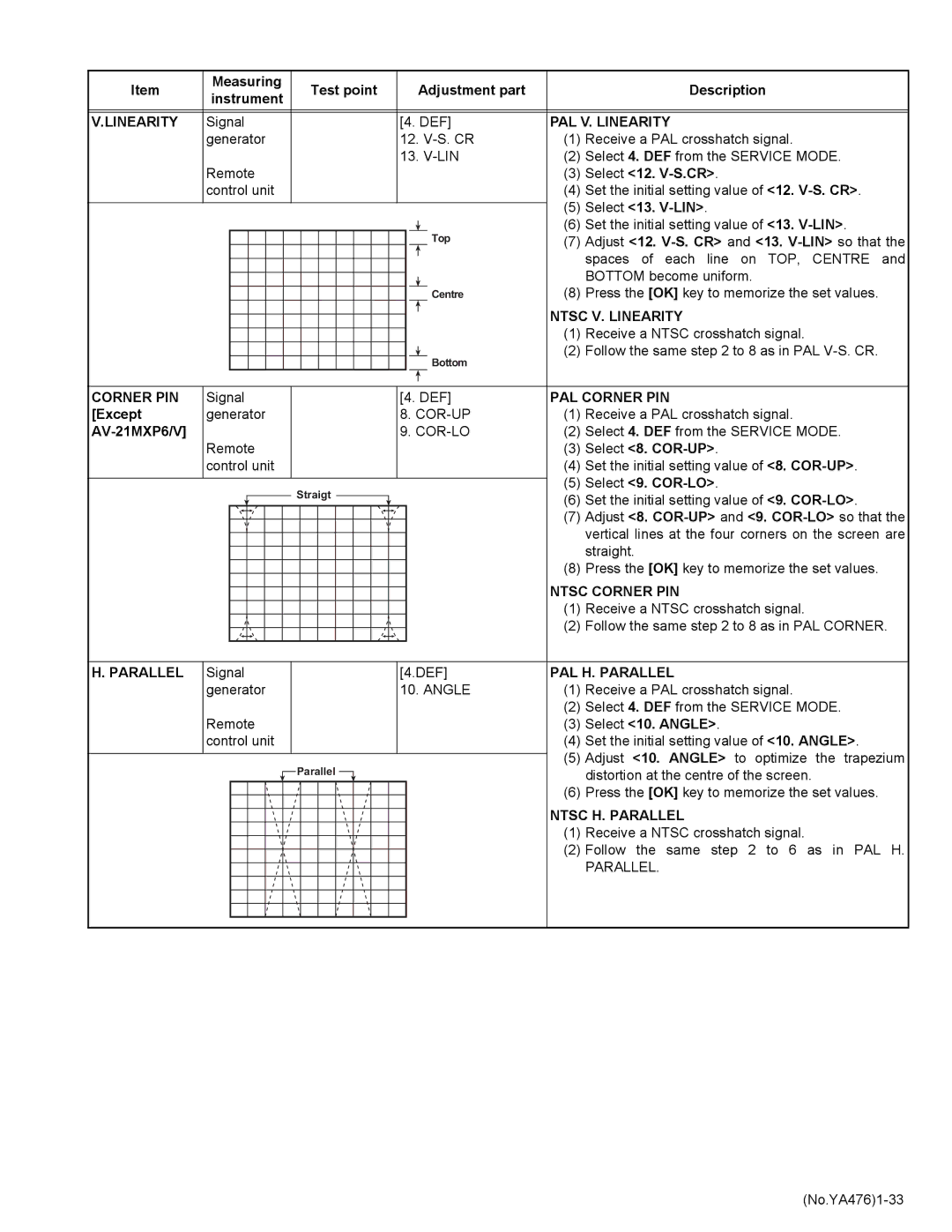
Measuring Test point Adjustment part Description Instrument
Adjustment Procedure Check Item
B1 Voltage
High Voltage HV voltmeter
Tuner / if Circuit
Delay Point
AGC
Focus
PAL V. Position
Position
Ntsc V. Position
Size
Ntsc H. Size
PAL H. Size
Side PIN
PAL Side PIN
PAL V. Linearity
Linearity
Ntsc V. Linearity
Corner PIN
BOW
PAL H. BOW
Ntsc H. BOW
PAL Trapezium PIN
Follow the same to 7 as in PAL Side PIN
Ntsc Trapezium PIN
Select 8. COR-UP
Video Circuit
„ Video 2 SET Component
White
Composite White Balance
SUB
SUB Bright
Contrast
SUB Colour
PAL Tint
SUB Tint
Ntsc 3.58 Tint
Ntsc 4.43 Tint
STANDARD, Soft and Theater
VSM Preset Setting
1. R Drive to 3. B Drive to the values
Warm and Normal
Purity and Convergence „ Purity Adjustment
„ Static Convergence Adjustment
„ Dynamic Convergence Adjustment
No.YA4761-41
Self Check Functions Outline
Indication by the Power LED
Self Check Items
Self Check Indicating Function
VPT
Copyright 2006 Victor Company of Japan, Limited
Schematic Diagrams
Indication of Parts Symbol Example
Safety
Indications on the Circuit Diagram
Specified Voltage and Waveform Values
AV-21MXP6/V, AV-25MXP6/V AV-29MXP6/V
Contents
Main PWB Pattern
2No.YA476
No.YA4762-32-4No.YA476
Main PWB
Front Control PWB1/2
No.YA4762-72-8No.YA476
Main PWB Circuit Diagram AV-21MXP6/V 1/4 2/4 SHEET1
No.YA4762-92-10No.YA476
Main PWB Circuit Diagram AV-21MXP6/V 3/44/4 SHEET2
No.YA4762-112-12No.YA476
Main PWB Circuit Diagram AV-25MXP6/V 1/4 2/4 Sheet
No.YA4762-132-14No.YA476
Main PWB Circuit Diagram AV-25MXP6/V 3/44/4 SHEET4
No.YA4762-152-16No.YA476
Main PWB Circuit Diagram AV-29MXP6/V 1/2 Sheet
No.YA4762-172-18No.YA476
Main PWB Circuit Diagram AV-29MXP6/V 2/2 Sheet
No.YA4762-192-20No.YA476
CRT Socket PWB Circuit Diagram AV-29MXP6/V Sheet
No.YA4762-212-22No.YA476
Front Control PWB Circuit Diagram AV-29MXP6/V Sheet
No.YA4762-232-24No.YA476
Bass PWB Circuit Diagram Sheet
No.YA4762-25 26No.YA476
Front
No.YA4762-272-28No.YA476
Main PWB Pattern AV-29MXP6/V
Bass PWB Pattern Solder Side
CRT Socket PWB Pattern AV-29MXP6/V
Bass PWB Pattern Parts Side
No.YA4762-292-30No.YA476
No.YA4762-312-32No.YA476
Front Control PWB Pattern AV-29MXP6/V
No.YA4762-332-34No.YA476
Voltage Charts AV-21MXP6/V, AV-25MXP6/V
No.YA4762-35
Waveforms AV-21MXP6/V, AV-25MXP6/V
Main PWB
36No.YA476
No.YA476
No.YA4763-1
Parts List
Contents
No.YA4763-3
Using P.W. Board & Remote Control Unit
100 V01 L01 101 102
106 103 105 104 T522
4No.YA476
No.YA4763-5
Printed Wiring Board Parts List
6No.YA476
No.YA4763-7
8No.YA476
No.YA4763-9
10No.YA476
487 5
No.YA4763-11
12No.YA476
V01 L01 100 101 102 106 103 105 104
No.YA4763-13
Main P.W. Board Assy SCW-1646A-H2
14No.YA476
No.YA4763-15
16No.YA476
No.YA4763-17
B Assy AV-29MXP6/V
18No.YA476
No.YA4763-19
V01 L01 100 101 103 DY01 2822 3018 102 40 T522
20No.YA476
Main P.W. Board Assy SCW-1647A-H2
No.YA4763-21
22No.YA476
No.YA4763-23
24No.YA476
CRT Socket P.W. Board Assy SCW-3037A-H2
No.YA4763-25
Bass P.W. Board Assy SCW-6003A-H2
Packing Packing Parts List
Colour Television
Do not allow objects or liquid into the cabinet openings
Main features
Knowing your TV’s features
No. Press
Remote control buttons and basic functions
Remote control buttons and basic functions
Front of the TV
TV buttons and functions
Turn off the equipment including the TV before connecting
Setting up your TV
Setting up your TV
Basic setting for picture
Picture Mode
Colour System
Picture Booster
Picture Setting White Balance
AI ECO Sensor ECO/ECO Mode
Advanced setting for picture
Compress
Blue Back
PIP
Original features for picture
Sound Mode
Basic setting for sound
Sound System
Balance
AI Volume
Advanced setting for sound
Cinema Surround
Equalizer
DVD Picture Mode
Auto Signal Detect
DVD Sound Mode
DVD Menu
Customized setting
Beep
VIDEO-2 Setting Display
Auto Program
TV channel presetting
Delete
TV channel presetting CH/CC number
Additional preparation
Before connecting
Troubleshooting
AV-25MXP6
Specifications
Model AV-29B316 AV-29M316 AV-29S356 AV-29B316BK