Additional preparation
The illustrations shown in this section are for
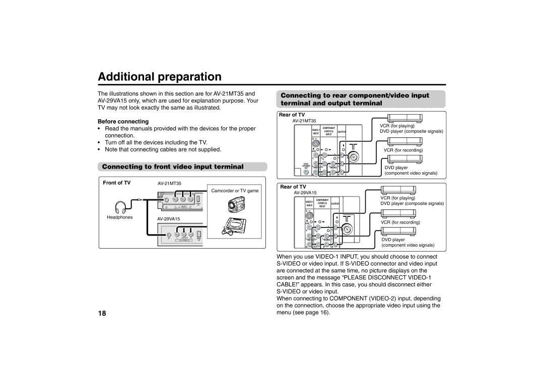
Connecting to rear component/video input terminal and output terminal
Before connecting
•Read the manuals provided with the devices for the proper connection.
•Turn off all the devices including the TV.
•Note that connecting cables are not supplied.
Connecting to front video input terminal
Rear of TV
| COMPONENT |
| ||||
|
| OUTPUT | ||||
| INPUT |
| ||||
|
| INPUT |
| |||
|
|
|
|
| ||
| S |
|
|
|
| |
| OVER |
|
|
|
| |
| V | Y/V |
|
| V | |
BASS | L |
|
| L |
| L |
SPEAKER | /MONO CB | /MONO | ||||
OUT |
|
|
| |||
R | CR | R | R |
VCR (for playing)
DVD player (composite signals)
VCR (for recording)
DVD player
(component video signals)
Front of TV
Headphones
|
| Rear of TV |
|
| ||
|
|
| Camcorder or TV game |
|
| |
|
|
|
| |||
|
|
|
|
| ||
|
|
|
| COMPONENT |
| |
|
| MENU |
| OUTPUT | ||
|
|
| INPUT | |||
|
| OK |
| INPUT |
| |
V | L / MONO | R |
|
| ||
| IN |
|
|
|
| |
|
|
|
| S |
|
|
OVER |
|
|
V | Y/V | V |
V L/MONO | R | MENU | L | /MONO CB | L | /MONO | L |
IN |
| OK |
|
|
|
R | CR | R | R |
VCR (for playing)
DVD player (composite signals)
VCR (for recording)
DVD player
(component video signals)
| When you use |
| |
| are connected at the same time, no picture displays on the |
| screen and the message “PLEASE DISCONNECT |
| CABLE!” appears. In this case, you should disconnect either |
|
|
| When connecting to COMPONENT |
| on the connection, choose the appropriate video input using the |
18 | menu (see page 16). |