3.2REPLACEMENT OF MEMORY IC
3.2.1 MEMORY IC
This TV uses the following memory IC.
Memory IC: IC702 on MAIN PWB
The memory IC memorizes data for correctly operating the video and deflection circuits. When replacing the memory IC, be sure to use the same type IC written with the initial values of data. In other words, use the specific IC listed in "PRINTED WIRING BOARD PARTS LIST". For its mounting location, refer to
"ADJUSTMENT LOCATIONS".
3.2.2 PROCEDURE FOR REPLACING MEMORY IC
1.Power off
Switch the power off and unplug the power cord from the wall outlet.
2.Replacing the memory IC
Replace the memory IC with new one. Be sure to use the memory IC written with the initial data values.
3.Power on
Plug the power cord into the wall outlet and switch the power on.
4.Check and setting of SYSTEM CONSTANT SET:
(1)Press the [DISPLAY] key and the [PICTURE MODE] key on the remote control unit simultaneously.
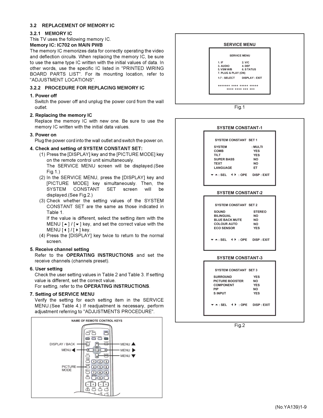
The SERVICE MENU screen will be displayed.(See Fig.1.)
(2)In the SERVICE MENU, press the [DISPLAY] key and [PICTURE MODE] key simultaneously. Then, the SYSTEM CONSTANT SET screen will be displayed.(See Fig.2.)
(3)Check whether the setting values of the SYSTEM
CONSTANT SET are the same as those indicated in Table 1.
If the value is different, select the setting item with the
MENU [ | ] / [ | ] key, and set the correct value with the |
MENU [ | ] / [ | ] key. |
(4)Press the [DISPLAY] key twice to return to the normal screen.
5.Receive channel setting
Refer to the OPERATING INSTRUCTIONS and set the receive channels (channels preset).
6.User setting
Check the user setting values in Table 2 and Table 3. If setting value is different, set the correct value.
For setting, refer to the OPERATING INSTRUCTIONS.
7.Setting of SERVICE MENU
Verify the setting for each setting item in the SERVICE MENU.(See Table 4.) If readjustment is necessary, perform adjustment referring to "ADJUSTMENTS PROCEDURE".
NAME OF REMOTE CONTROL KEYS
DISPLAY / BACK | MENU |
MENU![]()
![]()
![]()
![]()
![]() MENU
MENU ![]()
MENU ![]()
PICTURE ![]()
![]()
![]()
![]()
MODE
SERVICE MENU
SERVICE MENU
1. IF | 2. V/C |
3. AUDIO | 4. DEF |
5. VSM W/B | 6. S TATUS |
7. PLUG & PLAY (ON) | |
DISPLAY : EXIT | |
******* **** ***** *****
******** *** ***
Fig.1
SYSTEM
SYSTEM CONSTANT SET 1
SYSTEM | : MULTI |
COMB | YES |
TILT | YES |
SUPER BASS | NO |
TEXT | NO |
LANGUAGE | ET |
: SEL | : OPE DISP : EXIT |
SYSTEM CONSTANT-2
SYSTEM CONSTANT SET 2
SOUND |
| STEREO |
BILINGUAL |
| NO |
BLUE BACK MUTE | NO | |
COLOUR AUTO |
| NO |
ECO SENSOR |
| YES |
: SEL | : OPE | DISP : EXIT |
SYSTEM
SYSTEM CONSTANT SET 3
SURROUND |
| YES |
PICTURE BOOSTER | NO | |
COMPONENT |
| YES |
PIP |
| NO |
S INPUT |
| YES |
: SEL | : OPE | DISP : EXIT |
Fig.2