4.7ADJUSTMENT PROCEDURE
4.7.1 B1 VOLTAGE
Item |
| Measuring |
| Test point |
|
| Adjustment part |
| Description | ||||||||||
| instrument |
|
|
|
| ||||||||||||||
|
|
|
|
|
|
|
|
|
|
|
|
|
|
|
|
|
|
| |
|
|
|
|
|
|
|
|
|
|
|
|
|
|
|
|
|
|
| |
B1 VOLTAGE |
| Signal | B1 (pin 1) |
|
|
|
|
|
|
| (1) | Receive a black and white signal. | |||||||
check |
| generator | GND (pin 5) |
|
|
|
|
| (2) | Connect a DC voltmeter between B1 and GND | |||||||||
|
|
|
|
| [CN00X |
|
|
|
|
|
|
|
| (between pins 1 and 5 of the connector CN00X). | |||||
|
|
|
| DC voltmeter | connector in |
|
|
|
|
| (3) | Make sure that the voltage is DC134.5V ± 2V. | |||||||
|
|
|
|
| MAIN PWB] |
|
|
|
|
|
|
| |||||||
4.7.2 FOCUS ADJUSTMENT |
|
|
|
|
|
|
|
|
|
|
|
|
|
|
| ||||
|
|
|
|
|
|
|
|
|
|
|
|
|
|
|
|
|
|
|
|
Item |
| Measuring |
| Test point |
|
| Adjustment part |
| Description | ||||||||||
| instrument |
|
|
|
| ||||||||||||||
|
|
|
|
|
|
|
|
|
|
|
|
|
|
|
|
|
|
| |
|
|
|
|
|
|
|
|
|
|
|
|
|
|
|
|
|
|
| |
FOCUS |
| Signal |
|
|
|
|
|
|
|
|
|
| FOCUS VR | Notes: | |||||
adjustment |
| generator |
|
|
|
|
|
|
|
|
|
| [In HVT] | • Set PICTURE MODE (VSM) to "BRIGHT". | |||||
|
|
|
|
|
|
|
|
|
|
|
|
|
|
|
|
|
| • The final adjustment of CONVERGENCE must be | |
|
|
|
|
|
|
|
|
|
|
|
|
|
|
|
|
|
| done after the FOCUS adjustment. (CONVERGENCE | |
|
|
|
|
|
|
|
|
|
|
|
|
|
|
|
|
|
| is affected by the FOCUS adjustment.) | |
|
|
|
|
|
|
|
|
|
|
|
|
|
|
|
|
|
| If any aeviation in CONVERGENCE is found, PURITY | |
|
|
|
|
|
|
|
|
|
|
|
|
|
|
|
|
|
| must be adjusted to restore the convergence. | |
|
|
|
|
|
|
|
|
|
|
|
|
|
|
|
|
|
| (1) | Receive a crosshatch signal. |
|
|
|
|
|
|
|
|
|
|
|
|
|
|
|
|
|
| (2) | Adjust the FOCUS VR so that the vertical and |
|
|
|
|
|
|
|
|
|
|
|
|
|
|
|
|
|
|
| horizontal lines will be clear and in fine detail on the |
|
|
|
|
|
|
|
|
|
|
|
|
|
|
|
|
|
|
| screen. |
|
|
|
|
|
|
|
|
|
|
|
|
|
|
|
|
|
| (3) | Make sure that the picture is in focus even when the |
|
|
|
|
|
|
|
|
|
|
|
|
|
|
|
|
|
|
| screen gets darkened. |
|
|
|
|
|
|
|
|
|
|
|
|
|
|
|
|
|
| ||
4.7.3 IF CIRCUIT ADJUSTMENTS |
|
|
|
|
|
|
|
|
| ||||||||||
|
|
|
|
|
|
|
|
|
|
|
|
|
|
|
|
|
|
|
|
Item |
| Measuring |
| Test point |
|
| Adjustment part |
| Description | ||||||||||
| instrument |
|
|
|
| ||||||||||||||
|
|
|
|
|
|
|
|
|
|
|
|
|
|
|
|
|
|
| |
|
|
|
|
|
|
|
|
|
|
|
|
|
|
|
|
|
|
| |
IF VCO |
| Remote |
|
|
|
|
|
|
|
|
|
| [1. IF] | Note: | |||||
check |
| control unit |
|
|
|
|
|
|
|
|
|
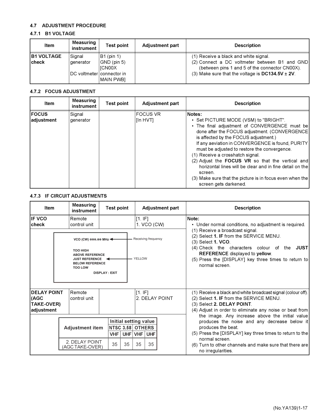
| 1. VCO (CW) | • Under normal conditions, no adjustment is required. | |||||
|
|
|
|
|
|
|
|
|
|
|
|
|
|
|
|
|
| (1) | Receive a broadcast signal. |
|
|
|
|
|
|
|
|
|
|
|
|
|
|
|
|
|
| ||
|
|
|
| VCO (CW) . |
|
|
|
|
|
|
|
|
| Receiving frequency | (2) | Select 1. IF from the SERVICE MENU. | |||
|
|
|
| MHz |
|
|
| (3) | Select 1. VCO. | ||||||||||
|
|
|
|
|
|
|
|
|
|
| |||||||||
|
|
|
|
|
|
|
|
|
|
|
|
|
|
|
|
|
| ||
|
|
|
| TOO HIGH |
|
|
|
|
|
|
|
|
|
|
|
|
| (4) | Check the characters colour of the JUST |
|
|
|
|
|
|
|
|
|
|
|
|
|
|
|
|
|
| REFERENCE displayed to yellow. | |
|
|
|
| ABOVE REFERENCE |
|
|
|
|
|
|
|
|
|
|
|
| (5) | ||
|
|
|
| JUST REFERENCE |
|
|
|
|
|
|
|
| YELLOW | Press the [DISPLAY] key three times to return to | |||||
|
|
|
| BELOW REFERENCE |
|
|
|
|
|
|
|
|
|
|
|
|
| normal screen. | |
|
|
|
| TOO LOW |
|
|
|
|
|
|
|
|
|
|
|
|
|
| |
|
|
|
|
|
|
|
|
|
|
|
|
|
|
|
|
|
|
| |
|
|
|
| DISPLAY : EXIT |
|
|
|
|
|
|
|
|
| ||||||
|
|
|
|
|
|
|
|
|
|
|
|
|
|
|
|
|
|
|
|
|
|
|
|
|
|
|
|
|
|
|
|
|
|
|
|
|
|
|
|
DELAY POINT |
| Remote |
|
|
|
|
|
|
|
|
|
| [1. IF] | (1) | Receive a black and white broadcast signal (colour off). | ||||
(AGC |
| control unit |
|
|
|
|
|
|
|
|
|
| 2. DELAY POINT | (2) | Select 1. IF from the SERVICE MENU. | ||||
|
|
|
|
|
|
|
|
|
|
|
|
|
|
|
| (3) | Select 2. DELAY POINT. | ||
adjustment |
|
|
|
|
|
|
|
|
|
|
|
|
|
|
| (4) | Adjust in order to eliminate any noise or beat from | ||
|
|
|
|
|
|
|
|
|
|
|
|
|
|
|
|
|
|
| the image. Any increase above the initial value |
|
|
|
|
|
|
|
|
|
|
|
|
|
|
|
|
|
|
| |
|
|
|
|
|
|
|
| Initial setting value |
|
| produces the noise and any decrease below it | ||||||||
|
|
| Adjustment item | NTSC 3.58 |
| OTHERS |
|
| produces the beat. | ||||||||||
|
|
|
|
|
|
|
| VHF |
| UHF | VHF | UHF |
| (5) | Press the [DISPLAY] key three times to return to the | ||||
|
|
|
|
|
|
|
|
|
|
|
|
|
|
|
|
|
|
| normal screen. |
|
|
|
|
|
|
|
|
|
|
|
|
|
|
|
|
|
|
| |
|
|
| 2. DELAY POINT |
| 35 |
| 35 |
| 35 | 35 |
|
| |||||||
|
|
|
|
|
|
| (6) | Turn to other channels and make sure that there are | |||||||||||
|
| (AGC |
|
|
|
| |||||||||||||
|
|
|
|
|
|
|
|
|
|
|
|
|
|
| no irregularities. | ||||
|
|
|
|
|
|
|
|
|
|
|
|
|
|
|
|
|
|
| |
|
|
|
|
|
|
|
|
|
|
|
|
|
|
|
|
|
|
|
|