4.7.8 PURITY AND CONVERGENCE
PURITY ADJUSTMENT
Note: |
|
|
|
|
|
|
| |
The final adjustment of CONVERGENCE must be done after | WEDGE | |||||||
the FOCUS adjustment. (CONVERGENCE is changed by |
| DEFLECTION | ||||||
| ||||||||
|
|
| YOKE | |||||
FOCUS adjustment.) |
|
|
| |||||
|
|
|
|
|
|
| ||
|
|
|
|
|
|
| ||
When makes difference by FOCUS adjustment, should be |
|
| P | |||||
reconfirming PURITY adjustment. |
|
| ||||||
CRT |
|
|
|
|
| |||
|
|
|
|
| ||||
|
|
|
|
| ||||
|
|
|
|
|
|
|
| |
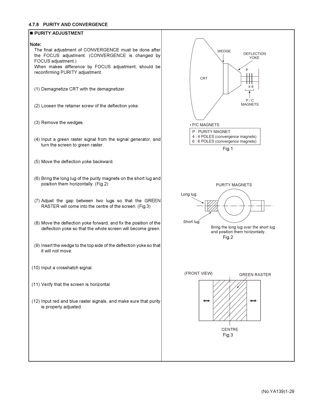
(1) Demagnetize CRT with the demagnetizer. | 4 6 |
|
| |||||
|
|
|
|
|
|
| ||
|
|
|
|
|
|
| ||
|
|
|
|
| ||||
|
|
| P / C | |||||
(2) Loosen the retainer screw of the deflection yoke. |
| MAGNETS | ||||||
|
|
|
|
|
|
| ||
(3) Remove the wedges. | • P/C MAGNETS | |||||||
| ||||||||
|
|
|
|
|
|
|
| |
| P : PURITY MAGNET |
| ||||||
(4) Input a green raster signal from the signal generator, and | 4 : 4 POLES (convergence magnets) |
| ||||||
6 : 6 POLES (convergence magnets) |
| |||||||
turn the screen to green raster. |
| |||||||
|
|
|
|
|
|
| ||
Fig.1 | ||||||||
| ||||||||
(5)Move the deflection yoke backward.
(6)Bring the long lug of the purity magnets on the short lug and
position them horizontally. (Fig.2) | PURITY MAGNETS |
Long lug
(7) Adjust the gap between two lugs so that the GREEN RASTER will come into the centre of the screen. (Fig.3)
(8) Move the deflection yoke forward, and fix the position of the | Short lug |
deflection yoke so that the whole screen will become green. | Bring the long lug over the short lug |
| and position them horizontally. |
| Fig.2 |
(9)Insert the wedge to the top side of the deflection yoke so that it will not move.
(10)Input a crosshatch signal.
| (FRONT VIEW) | GREEN RASTER |
|
| |
(11) | Verify that the screen is horizontal. |
|
(12) | Input red and blue raster signals, and make sure that purity |
|
| is properly adjusted. |
|
|
| CENTRE |
|
| Fig.3 |
