BEFORE STARTING
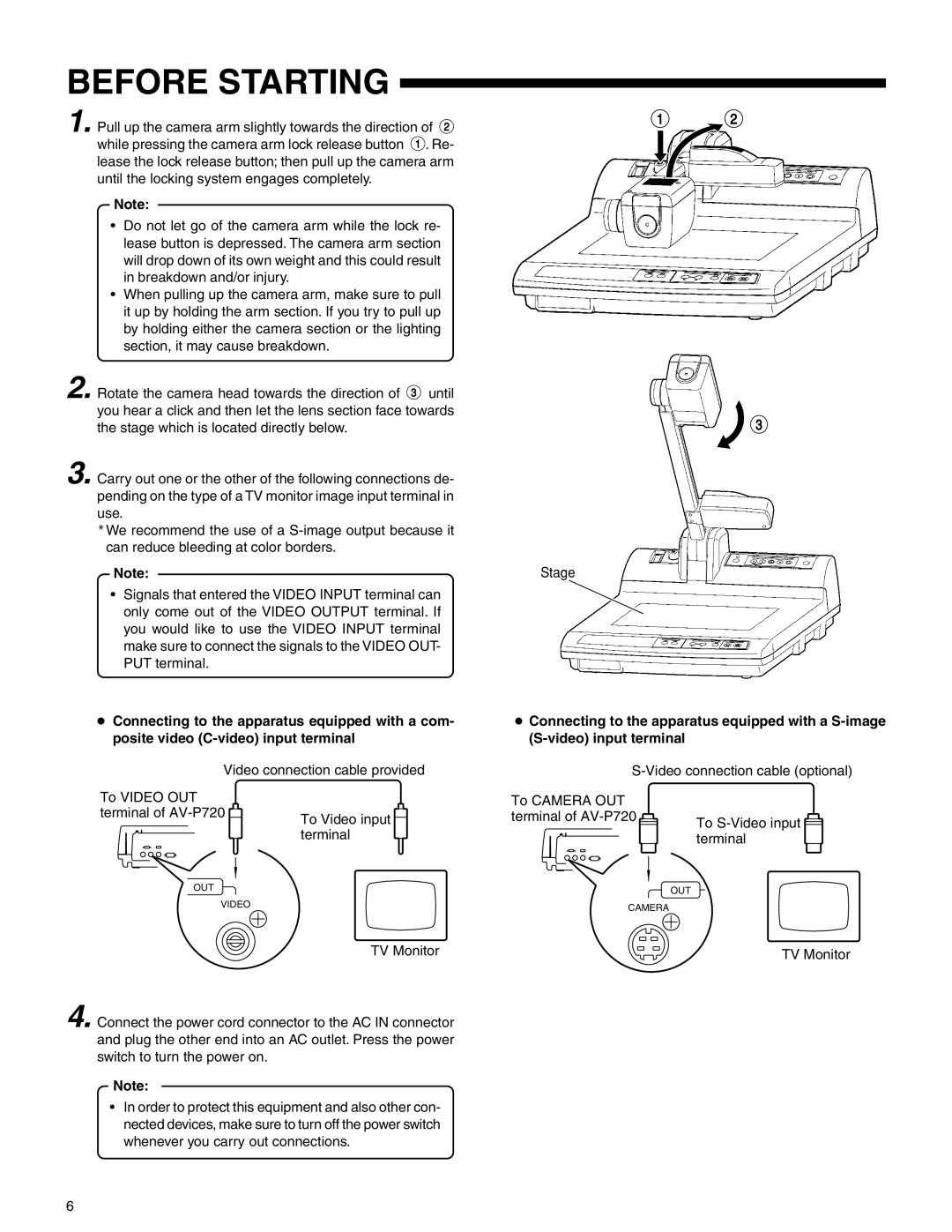
1. Pull up the camera arm slightly towards the direction of 2 while pressing the camera arm lock release button 1. Re- lease the lock release button; then pull up the camera arm until the locking system engages completely.
Note:
•Do not let go of the camera arm while the lock re- lease button is depressed. The camera arm section will drop down of its own weight and this could result in breakdown and/or injury.
•When pulling up the camera arm, make sure to pull it up by holding the arm section. If you try to pull up by holding either the camera section or the lighting section, it may cause breakdown.
2.Rotate the camera head towards the direction of 3 until you hear a click and then let the lens section face towards the stage which is located directly below.
3.Carry out one or the other of the following connections de- pending on the type of a TV monitor image input terminal in use.
*We recommend the use of a
Note:
•Signals that entered the VIDEO INPUT terminal can only come out of the VIDEO OUTPUT terminal. If you would like to use the VIDEO INPUT terminal make sure to connect the signals to the VIDEO OUT- PUT terminal.
●Connecting to the apparatus equipped with a com- posite video
Video connection cable provided
12
![]() 3
3
Stage
●Connecting to the apparatus equipped with a
To VIDEO OUT terminal of ![]()
To Video input terminal
To CAMERA OUT terminal of ![]()
![]()
To ![]() terminal
terminal
OUT
OUT
VIDEO
TV Monitor
4. Connect the power cord connector to the AC IN connector and plug the other end into an AC outlet. Press the power switch to turn the power on.
Note:
•In order to protect this equipment and also other con- nected devices, make sure to turn off the power switch whenever you carry out connections.
CAMERA
TV Monitor
6