NAMES AND FUNCTIONS | – Front panel – |
OF VARIOUS PARTS |
OPERATE |
|
|
1 |
|
|
Mini |
| A.DUB |
PROFESSIONAL |
| |
MIC | REMOTE SEL. | INPUT SEL. |
| SERIAL | LINE |
| 9PIN WIRELESS | DV Y/C |
2 |
|
| |
|
| EJECT | |
|
| MENIU | |
REC | PLAY | PAUSE | |
DVCAM NTSC PAL REC INH. |
|
| |
| SET | ||
REW | STOP | ||
FF | |||
|
| ||
|
|
|
OPERATE
| Mini | A.DUB |
PROFESSIONAL |
| |
MIC | REMOTE SEL. | INPUT SEL. |
| SERIAL | LINE |
| 9PIN WIRELESS | DV Y/C |
|
| EJECT | |
|
| 7 | |
|
| MENIU | |
REC | PLAY | PAUSE | |
DVCAM NTSC PAL REC INH. |
|
| |
| SET | ||
REW | STOP | ||
FF | |||
|
| ||
|
|
4 3
6 | 5 |
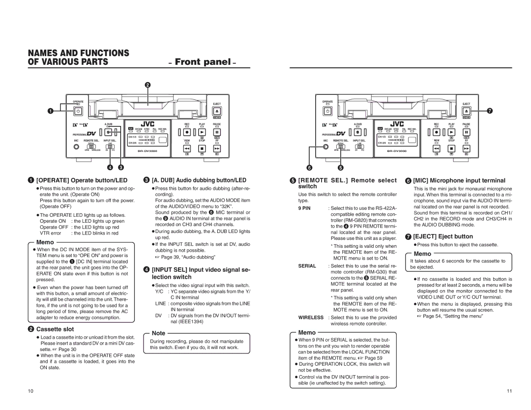
1 | [OPERATE] Operate button/LED | |
| ||
| ● Press this button to turn on the power and op- | |
| erate the unit. (Operate ON) | |
| Press this button again to turn off the power. | |
| (Operate OFF) | |
| ● The OPERATE LED lights up as follows. | |
| Operate ON | : the LED lights up green |
| Operate OFF | : the LED lights up red |
| VTR error | : the LED blinks in red |
| Memo |
|
●When the DC IN MODE item of the SYS- TEM menu is set to “OPE ON” and power is
supplied to the 1 [DC IN] terminal located at the rear panel, the unit goes into the OP- ERATE ON state even if this button is not pressed.
● Even when the power has been turned off with this button, a small amount of electric- ity will still be channeled into the unit. There- fore, if the unit is not going to be used for a long period of time, please remove the AC adapter to reduce energy consumption.
2 | Cassette slot |
| |
| ● Load a cassette into or unload it from the slot. |
| Please insert a standard DV or a mini DV cas- |
| sette. ☞ Page 30 |
| ● When the unit is in the OPERATE OFF state |
| and if a cassette is loaded, it goes into the |
| ON state. |
3 | [A. DUB] Audio dubbing button/LED | |||
| ||||
| ● Press this button for audio dubbing | |||
| cording). | |||
| For audio dubbing, set the AUDIO MODE item | |||
| of the AUDIO/VIDEO menu to “32K”. | |||
| Sound produced by the 6 MIC terminal or | |||
| the | 9 | AUDIO IN terminal at the rear panel is | |
|
|
| ||
| recorded on CH3 and CH4 channels. | |||
| ● During audio dubbing, the A. DUB LED lights | |||
| up red. | |||
| ● If the INPUT SEL switch is set at DV, audio | |||
| dubbing is not possible. | |||
| ☞ Page 39, “Audio dubbing” | |||
4 | [INPUT SEL] Input video signal se- | |||
| ||||
| lection switch | |||
| ● Select the video signal input with this switch. | |||
| Y/C | : YC separate video signals from the Y/ | ||
|
|
|
| C IN terminal |
| LINE : composite video signals from the LINE | |||
|
|
|
| IN terminal |
| DV |
| : DV signals from the DV IN/OUT termi- | |
|
|
|
| nal (IEEE1394) |
| Note |
|
| |
| During recording, please do not manipulate | |||
| this switch. Even if you do, it will not work. | |||
5 | [REMOTE SEL.] Remote select | |||
| switch |
|
|
|
| Use this switch to select the remote controller | |||
| type. |
|
|
|
| 9 PIN | : Select this to use the | ||
|
| compatible editing remote con- | ||
|
| troller | ||
|
| to the | 4 | 9 PIN REMOTE termi- |
|
|
| ||
|
| nal located at the rear panel. | ||
|
| Please use this unit as a player. | ||
|
| * This setting is valid only when | ||
|
| the REMOTE item of the RE- | ||
|
| MOTE menu is set to ON. | ||
| SERIAL | : Select this to use the serial re- | ||
|
| mote controller | ||
|
| connects to the 3SERIAL RE- | ||
|
| MOTE terminal located at the | ||
|
| rear panel. | ||
|
| * This setting is valid only when | ||
|
| the REMOTE item of the RE- | ||
|
| MOTE menu is set to ON. | ||
| WIRELESS | : Select this to use the provided | ||
|
| wireless remote controller. | ||
Memo ● When 9 PIN or SERIAL is selected, the but- tons on the unit you wish to render operable can be selected from the LOCAL FUNCTION item of the REMOTE menu. ☞ Page 59
● During OPERATION LOCK, this switch will not be effective. ● Control via the DV IN/OUT terminal is pos- sible (ie unaffected by the switch setting).
6 | [MIC] Microphone input terminal |
| |
| This is the mini jack for monaural microphone |
| input. When this terminal is connected to a mi- |
| crophone, sound input via the AUDIO IN termi- |
| nal located on the rear panel is not recorded. |
| Sound from this terminal is recorded on CH1/ |
| CH2 in the RECORD mode and CH3/CH4 in |
| the AUDIO DUBBING mode. |
7 | [EJECT] Eject button |
| |
| ● Press this button to eject the cassette. |
Memo It takes about 6 seconds for the cassette to be ejected.
●If no cassette is loaded and this button is pressed for at least 2 seconds, a menu will be displayed on the monitor connected to the VIDEO LINE OUT or Y/C OUT terminal.
●When the menu is displayed, pressing this button will resume the usual screen.
☞ Page 54, “Setting the menu”
10
11