AM antenna
| ANTENNA | |
|
| (not supplied) |
1 | AM EXT |
|
AM LOOP |
|
FM 75![]()
COAXIAL
2
AM loop antenna (supplied)
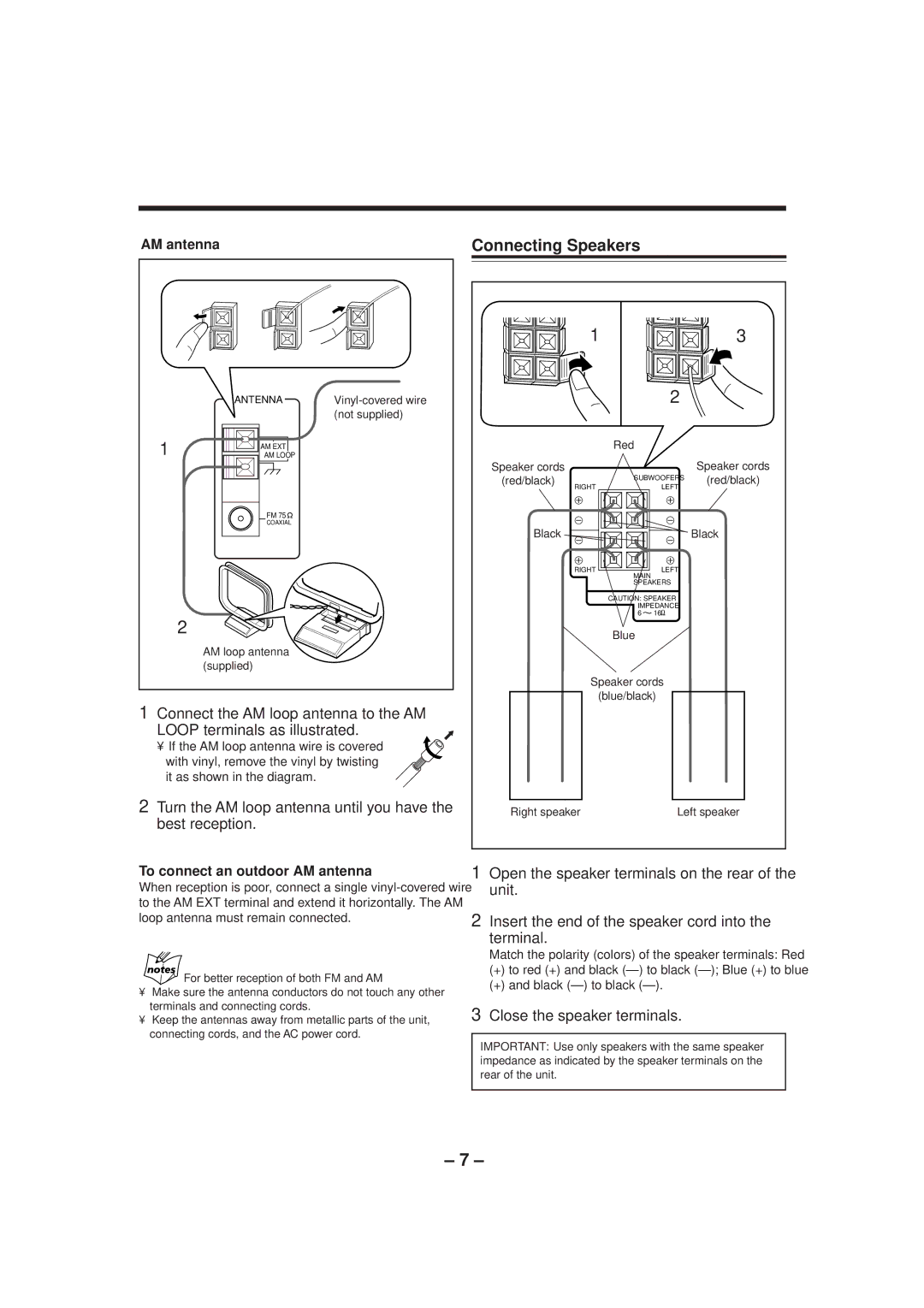
1Connect the AM loop antenna to the AM
LOOP terminals as illustrated.
• If the AM loop antenna wire is covered with vinyl, remove the vinyl by twisting it as shown in the diagram.
2Turn the AM loop antenna until you have the best reception.
Connecting Speakers
| 1 |
| 3 | |
|
| 2 | ||
| Red |
|
| |
Speaker cords | SUBWOOFERS | Speaker cords | ||
(red/black) | (red/black) | |||
RIGHT | LEFT | |||
|
| |||
Black |
|
| Black | |
| RIGHT | LEFT |
| |
| MAIN |
|
| |
| SPEAKERS |
| ||
| CAUTION: SPEAKER |
| ||
| IMPEDANCE |
| ||
| 6 | 16 |
| |
| Blue |
|
| |
| Speaker cords |
| ||
| (blue/black) |
| ||
Right speaker |
| Left speaker | ||
To connect an outdoor AM antenna
When reception is poor, connect a single
For better reception of both FM and AM
•Make sure the antenna conductors do not touch any other terminals and connecting cords.
•Keep the antennas away from metallic parts of the unit, connecting cords, and the AC power cord.
1Open the speaker terminals on the rear of the unit.
2Insert the end of the speaker cord into the
terminal.
Match the polarity (colors) of the speaker terminals: Red
(+)to red (+) and black
(+)and black
3Close the speaker terminals.
IMPORTANT: Use only speakers with the same speaker impedance as indicated by the speaker terminals on the rear of the unit.
– 7 –