Getting Started
Names and Functions of Parts (Cont’d)
Rear
F G H I J
Q P
O
DVI 1 |
|
DVI 2 |
|
CONTROL |
|
USB | Exhaust air |
LAN | |
DVI 3 |
|
| OPERATE I/B STANDBY/ON |
| LAMP |
DVI 4 | WARNING |
|
N M L K
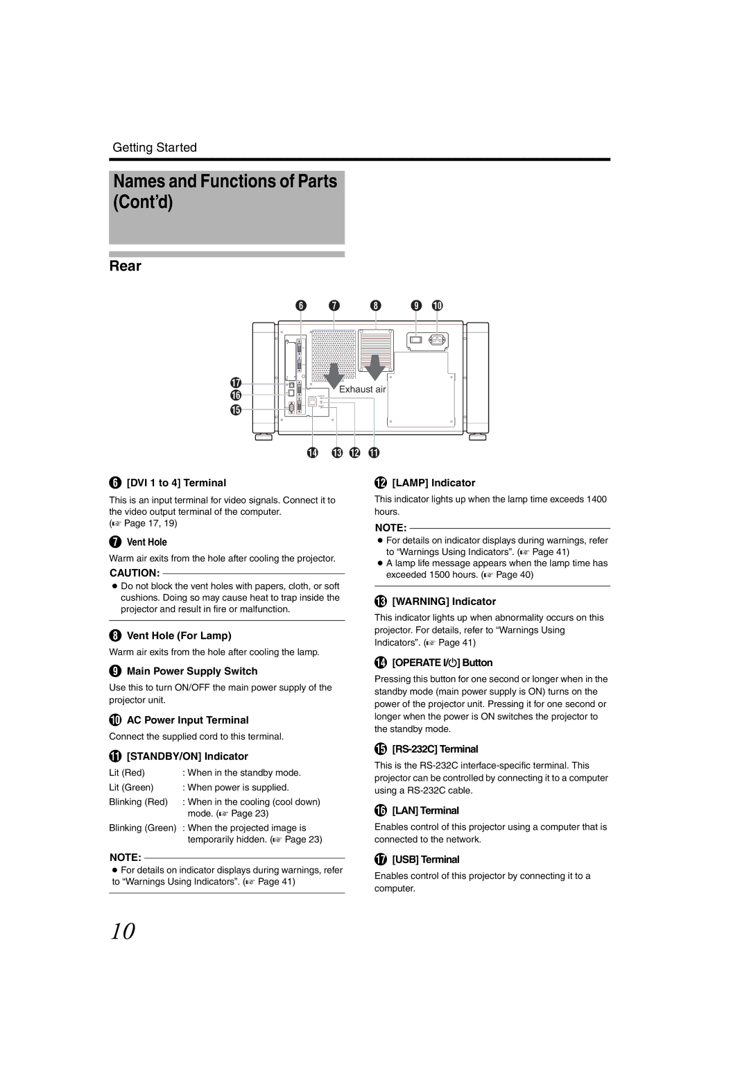
F[DVI 1 to 4] Terminal
This is an input terminal for video signals. Connect it to the video output terminal of the computer.
(A Page 17, 19)
GVent Hole
Warm air exits from the hole after cooling the projector.
CAUTION:
●Do not block the vent holes with papers, cloth, or soft cushions. Doing so may cause heat to trap inside the projector and result in fire or malfunction.
HVent Hole (For Lamp)
Warm air exits from the hole after cooling the lamp.
IMain Power Supply Switch
Use this to turn ON/OFF the main power supply of the projector unit.
JAC Power Input Terminal
Connect the supplied cord to this terminal.
K[STANDBY/ON] Indicator
Lit (Red) | : When in the standby mode. |
Lit (Green) | : When power is supplied. |
Blinking (Red) | : When in the cooling (cool down) |
| mode. (A Page 23) |
Blinking (Green) : When the projected image is temporarily hidden. (A Page 23)
L[LAMP] Indicator
This indicator lights up when the lamp time exceeds 1400 hours.
NOTE:
●For details on indicator displays during warnings, refer to “Warnings Using Indicators”. (A Page 41)
●A lamp life message appears when the lamp time has exceeded 1500 hours. (A Page 40)
M[WARNING] Indicator
This indicator lights up when abnormality occurs on this projector. For details, refer to “Warnings Using Indicators”. (A Page 41)
N[OPERATE I/B] Button
Pressing this button for one second or longer when in the standby mode (main power supply is ON) turns on the power of the projector unit. Pressing it for one second or longer when the power is ON switches the projector to the standby mode.
O[RS-232C] Terminal
This is the
P[LAN] Terminal
Enables control of this projector using a computer that is connected to the network.
NOTE:
●For details on indicator displays during warnings, refer to “Warnings Using Indicators”. (A Page 41)
Q[USB] Terminal
Enables control of this projector by connecting it to a computer.
10
