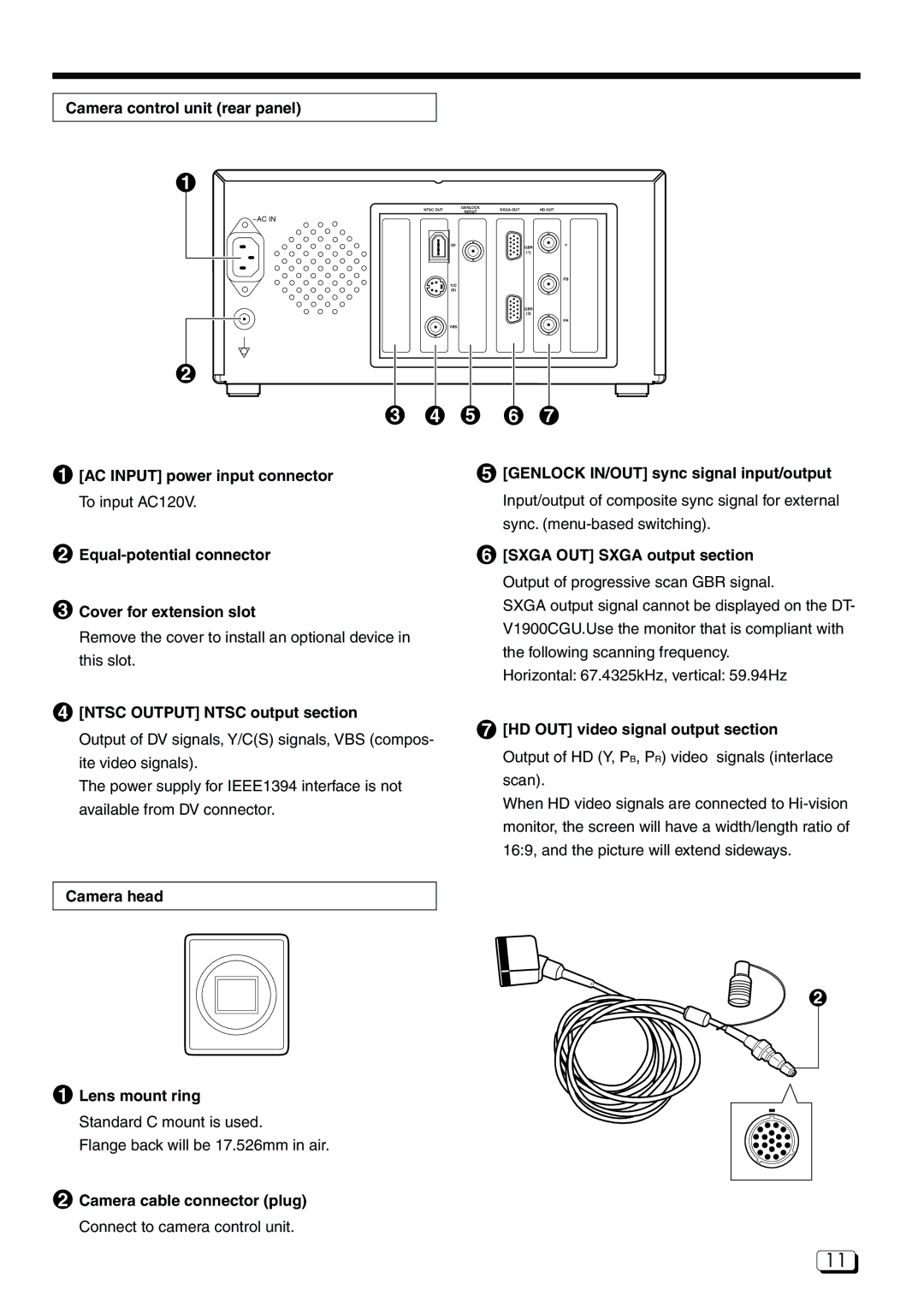
Camera control unit (rear panel)
1
~AC IN
NTSC OUT | GENLOCK | SXGA OUT |
| HD OUT |
IN/OUT |
| |||
|
|
|
| |
DV |
|
| GBR | Y |
|
|
|
| |
|
|
| (1) |
|
|
|
|
| PB |
Y/C |
|
|
|
|
(S) |
|
|
|
|
|
|
| GBR |
|
|
|
| (2) |
|
|
|
|
| PR |
VBS |
|
|
|
|
2
3 4
1[AC INPUT] power input connector To input AC120V.
2
3Cover for extension slot
Remove the cover to install an optional device in this slot.
4[NTSC OUTPUT] NTSC output section
Output of DV signals, Y/C(S) signals, VBS (compos- ite video signals).
The power supply for IEEE1394 interface is not available from DV connector.
5 6 7
5[GENLOCK IN/OUT] sync signal input/output Input/output of composite sync signal for external sync.
6[SXGA OUT] SXGA output section Output of progressive scan GBR signal.
SXGA output signal cannot be displayed on the DT- V1900CGU.Use the monitor that is compliant with the following scanning frequency.
Horizontal: 67.4325kHz, vertical: 59.94Hz
7[HD OUT] video signal output section
Output of HD (Y, PB, PR) video signals (interlace scan).
When HD video signals are connected to
Camera head
2
1Lens mount ring
Standard C mount is used.
Flange back will be 17.526mm in air.
2Camera cable connector (plug) Connect to camera control unit.
11