ENGLISH
‰∑¬
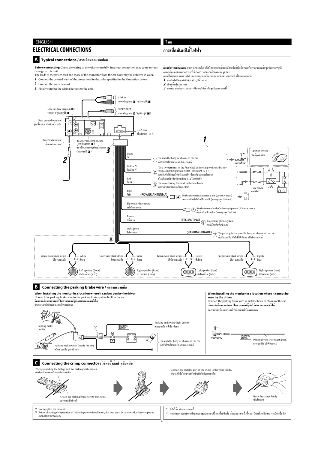
ELECTRICAL CONNECTIONS |
|
| °“√‡™◊ËÕ¡‚¥¬„™È‰øøÈ“ |
| ||||
A Typical connections / °“√‡™◊ËÕ¡µËÕ·∫∫ª°µ |
|
|
|
|
|
| ||
Before connecting: Check the wiring in the vehicle carefully. Incorrect connection may cause serious | °ËÕ•∑”°“•‡™•ËÕ¡µËÕ: | |||||||
damage to this unit. |
|
|
|
| °“•‡™•ËÕ¡µËÕº‘¥æ•“¥Õ“®∑”„Àȇ°‘¥§«“¡‡ ¬À“¬•È“¬·•ß°’ | •™ÿ— ¥ª•– | ||
The leads of the power cord and those of the connector from the car body may be different in color. | ||||||||
1 Connect the colored leads of the power cord in the order specified in the illustration below. |
| 1 µËÕ “¬‰ø µ“¡≈”’ | ¥∫∑’Ë√— |
| ||||
2 Connect the antenna cord. |
|
|
|
| 2 ‡™◊ËÕ¡µËÕ°∫“¬Õ“°“»— |
|
| |
3 Finally connect the wiring harness to the unit. |
|
| 3 ¥ÿ∑È“¬ µËÕ «π§«∫§ÿ¡°“√‡Ë | ¥‘𠓬‰ø‡¢È“°∫™ÿ— | ||||
|
| LINE IN | / ¥Ÿ·ºπ¿Ÿ¡‘ |
|
|
|
|
|
|
| (see diagram | ) |
|
|
|
| |
Line out (see diagram ) |
| VIDEO OUT |
|
|
|
|
|
|
“¬ÕÕ° (¥Ÿ·ºπ¿Ÿ¡‘ ) |
| (see diagram | / ¥Ÿ·ºπ¿Ÿ¡‘ | ) |
|
|
|
|
Rear ground terminal |
|
|
|
|
|
|
|
|
®ÿ¥‡™◊ËÕ¡µËÕ “¬¥‘π¥È“πÀ≈ß— |
|
|
|
|
|
|
|
|
|
|
| 15 A fuse |
|
|
|
|
|
|
|
| ø‘« Ï¢π“¥ 15 A |
|
|
|
| |
Antenna terminal | To external components |
|
|
|
|
|
| |
(see diagram | ) |
|
|
|
|
|
| |
| ™ËÕ߇ ¬∫µËÕ’ ¢ÕßÕÿª°√≥Ï¿“¬πÕ° |
|
|
|
|
|
| |
| (¥Ÿ·ºπ¿Ÿ¡‘ | ) |
|
|
|
|
| Ignition switch |
|
| Black |
|
|
|
|
|
|
|
| ’¥” |
|
| To metallic body or chassis of the car | |||
|
|
|
|
| ||||
|
|
|
|
|
|
| ||
Yellow *2
‡À≈◊Õß’ *2
Red
·’¥ß
Blue
»’øÈ“
Blue with white stripe
To a live terminal in the fuse block connecting to the car battery (bypassing the ignition switch) (constant 12 V)
(‚¥¬‰¡ËµÈÕß„™È«
To an accessory terminal in the fuse block
To the automatic antenna if any (250 mA max.)
‡
Fuse block
·ºßø‘«
πÈ”‡ß‘π≈“¬¢“«
Brown
πÈ”µ“≈’
Light green
To the remote lead of other equipment (200 mA max.)
µËÕ‡¢È“°∫Õª°√≥ÏÕË◊π— (¢π“¥ Ÿß ¸¥ 200 mA)
To cellular phone system
‡’¢’¬«ÕËÕπ
White with black stripe | White | Gray with black stripe | Gray | Green with black stripe | |
¢’“«·∂∫¥” | ’¢“« | ‡∑“·∂∫’ | ¥” | ’‡∑“ | ‡’¢’¬«·∂∫¥” |
| Left speaker (front) |
| Right speaker (front) | ||
| ≈”‚æß´È“¬ (ÀπÈ“) |
|
| ≈”‚æߢ«“ (ÀπÈ“) |
|
To parking brake, metallic body or chassis of the car
µËÕ°∫‡∫√°¡◊Õ—
Green | Purple with black stripe | Purple | |
’‡¢’¬« | ¡Ë«ß·∂∫’ | ¥” | ’¡Ë«ß |
Left speaker (rear) |
|
| Right speaker (rear) |
≈”‚æß´È“¬ (À≈ß)— |
|
| ≈”‚æߢ«“ (À≈ß)— |
BConnecting the parking brake wire / µËÕ “¬‡∫√°¡◊Õ
When installing the monitor in a location where it can be seen by the driver
Connect the parking brake wire to the parking brake system built in the car.
¡◊ËÕ®–µ‘¥µß®Õ¡Õ𑇵Õ√Ï„πµ”·ÀπËß∑’˺ŸÈÈ— ¢∫— “¡“√∂¡Õ߇ÀÁπ‰¥È
µËÕ
Parking brake
‡∫√°¡◊Õ
Parking brake switch (inside the car)
«‘µ™Ï‡∫√°¡◊Õ (¿“¬„π√∂)
Parking brake wire (light green)
“¬‡∫√°¡◊Õ ( ‡’¢’¬«ÕàÕπ)
To metallic body or chassis of the car
When installing the monitor in a location where it cannot be seen by the driver
Connect the parking brake wire to metallic body or chassis of the car.
µËÕ
Parking brake wire (light green)
“¬‡∫√°¡◊Õ ( ‡’¢’¬«ÕàÕπ)
CConnecting the crimp connector / «‘∏’µËÕ¢«µËÕÈ— ”À√∫Àπ’∫—
Wire connecting the battery and the parking brake switch.
Contact the metallic part of the crimp to the wires inside.
Attach the parking brake wire to this point. | Pinch the crimp firmly. |
Õ “¬‡∫√°¡◊Õ∑’Ë®ÿ¥π’È | Àπ’∫„ÀÈ·πËπ |
*1 Not supplied for this unit.
*2 Before checking the operation of this unit prior to installation, this lead must be connected, otherwise power cannot be turned on.
*1 ‰¡Ë‰¥È„ÀÈ¡“°∫™ÿ—
*2 °ËÕπ°“√µ√«®
3