Page
00080928811
Safety Instructions
Safety Instructions for the Installer
Table of Contents
Outline Drawings
Word to the Owner of the GP-37, GP-32
Features
Foreword
GP-32 system configuration
System Configuration
GP-37 system configuration
Msas Egnos Waas
What is WAAS?
Standard supply
Equipment Lists
Optional equipment
Name Type Code No Qty Remarks
Operational Overview
How to attach and remove the hard cover
Controls
Control panel
Adjusting Brilliance and Contrast
Turning On and Off Power
Turning on the power
Turning off the power
Display Modes
Display modes default user displays
Highway display
Plotter display
Plotter display
Highway display
Nav data display
Steering display
Steering display
Nav data display
User displays
Digital display default display
Digital display
Speedometer display
Menu Overview
How to enter alphanumeric data
OFF
Auto
Simulator display, auto course selected
Simulation Display
Simulator menu
Choosing the Display Range
Plotter Display Overview
Shifting the Cursor
Cursor state and data
Centering Own Ship’s Position
Shifting the Display
Changing Track Plotting Interval, Stopping Plotting
OFF
Erase menu
Erasing Track
Erase Track
YES
Plotter Display Overview This page intentionally left blank
Entering a waypoint with the cursor
Waypoints Marks
Entering Waypoints
Entering a waypoint from the waypoint list
Entering a waypoint at own ship position
WPTS/MARKS List
GPS POS. → Mark
Enter a NEW WPT Name
Entering the MOB Mark
Mark
Saved to MOB GO to MOB ?
Operations on the Waypoint List
Displaying Waypoint Name
DSP RTE DSP ALL
Editing waypoints
Showing nearest waypoints by distance, TTG and ETA
Erasing Waypoints
WPTS/MARKS Nearest
Name Kobe
Speed for Calculating Time-to-Go, Estimated Time of Arrival
Creating Routes
Routes
Creating a route with the cursor
Sample route
Creating a route from the route menu
Routes
WPTS/MARKS List
Creating a route from the waypoint list
Routes
Creating a track-based route manually
Creating a track-based route
Creating a track-based route automatically
Distance
Replacing waypoints in a route
Editing Routes
REMOVE? INSERT? SKIP?
Name
Permanently deleting a waypoint from a route
Route contents Route-01
Inserting a waypoint in a route
Temporarily deselecting a waypoint in a route
Changing route comment name
Erasing Routes
Erase Route 01 ?
YES
This page intentionally left blank
Setting Destination by Waypoint
Setting Destination by Cursor
WPT-NEAR? OFF?? ROUTE? CURSOR? SETUP?
Destination
Setting User Waypoint as Destination
Setting Route as Destination
Canceling Destination
REVERSE?
Arrival Alarm, Anchor Watch Alarm
Alarms
Arrival alarm
Alarms
ARV ANC
XTE Cross Track Error Alarm
Anchor watch alarm
WAAS/DGPS Alarm
Speed Alarm
Time Alarm
WAAS/DGPS mode and alarm message
Odometer Alarm
Trip Alarm
Buzzer Type Selection
Long Constant
Calculating Range, Bearing, TTG and ETA
Other Functions
Range and bearing between two waypoints
Route
GPS
Waas Setup
Waas INT Beacon
EXT Beacon
GPS
Dgps setup
Editing Dgps user channels
Programming Dgps user channels stations
Station Nearest
Station User
Erasing all user channels
Bearing Reference
True
Erasing individual user channels
Units of Measurement
Geodetic Chart System
Magnetic Variation
Position Display Format
Time Difference using local time, Time Format
For Loran C TD
For Decca TD
GPS Setup menu description
GPS Setup
Speedometer
User Display Setup
Digital data
Reset Trip METER? Are YOU SURE? YES no ODOMETER?
Resetting Trip and Odometer Distances
Reset trip meter, odometer options
Speedometer display
Setting for communication software on
Wiring
Uploading, Downloading Waypoint, Route Data
Downloading/Uploading between PC and GP-37/GP-32
Loading data from a Yeoman
Uploading data from a PC
Route data format
Waypoint data format
Route comment data format
Language
End of sentence
Espanol
Maintenance
Maintenance & Troubleshooting
Displaying the Message Board
Messages
Exchange BATTERY?
Replacing the Battery
Ready for Battery Change Press ANY KEY To Shut Down
Replacing the Fuse
Satellite Monitor Display
Diagnostics
Satellite monitor display
Test START? prompt
Clearing Data
Language Default Position Unit Time Difference
Language and default position, unit and time difference
This page intentionally left blank
Installation of Display Unit
Installation
Mounting considerations
Desktop and overhead mounting
How to assemble the connector
Installation of Antenna Unit
Flush mount S kit
Flush mount S kit Type OP20-17 Code No
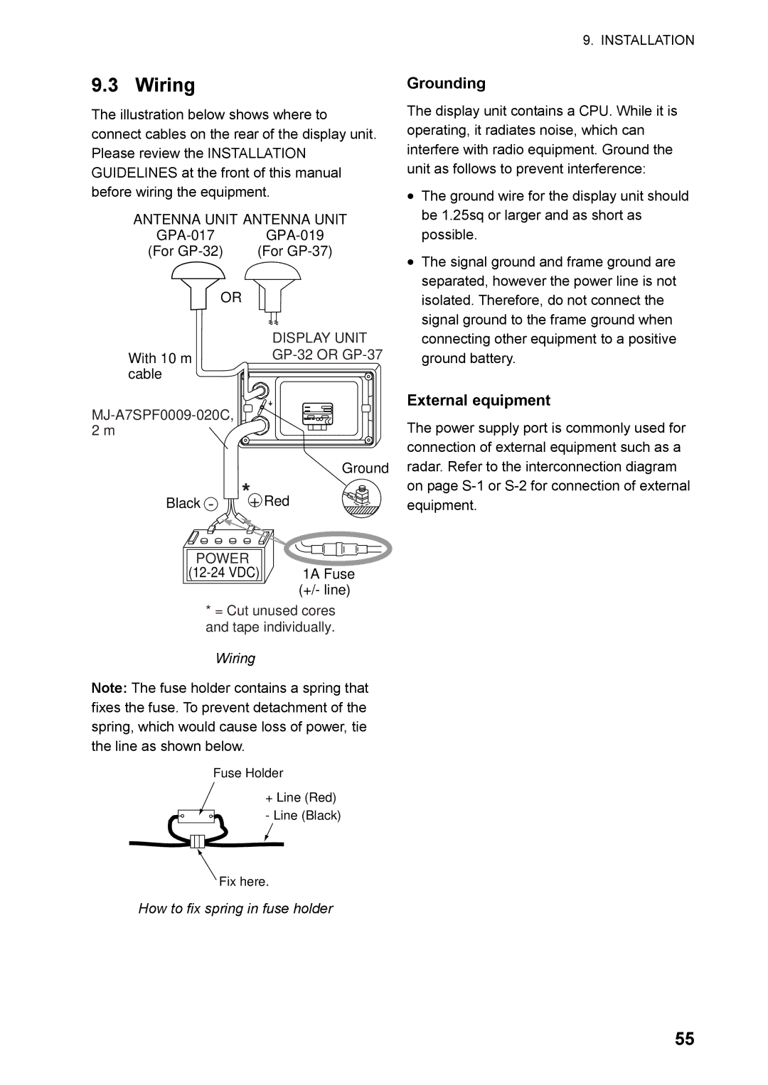
Wiring
Wiring
How to fix spring in fuse holder
Grounding
Output data format, data sentences
Initial Settings
DATA1 Current loop data
DATA2 RS-232C level
DATA1, Data 2 and Nmea version options
Output setting
Setup menu
This page intentionally left blank
Menu Tree
Appendix
Available data Odometer, trip , time
Digital Display division
Start from -99 to +99
Interval 01 to 99
North American
Geodetic Chart List
GRI
Loran C Chains
Chain Location Code
Decca Chains
AP-6
Specifications GPS Navigator GP-32 Dgps Navigator GP-37
Power Supply
CT������4�UWOK
Feb
Hatai
Page
Page
Page
GPS Navigator
Dgps Navigator
WAAS/DGPS XTE
Index
Index-2