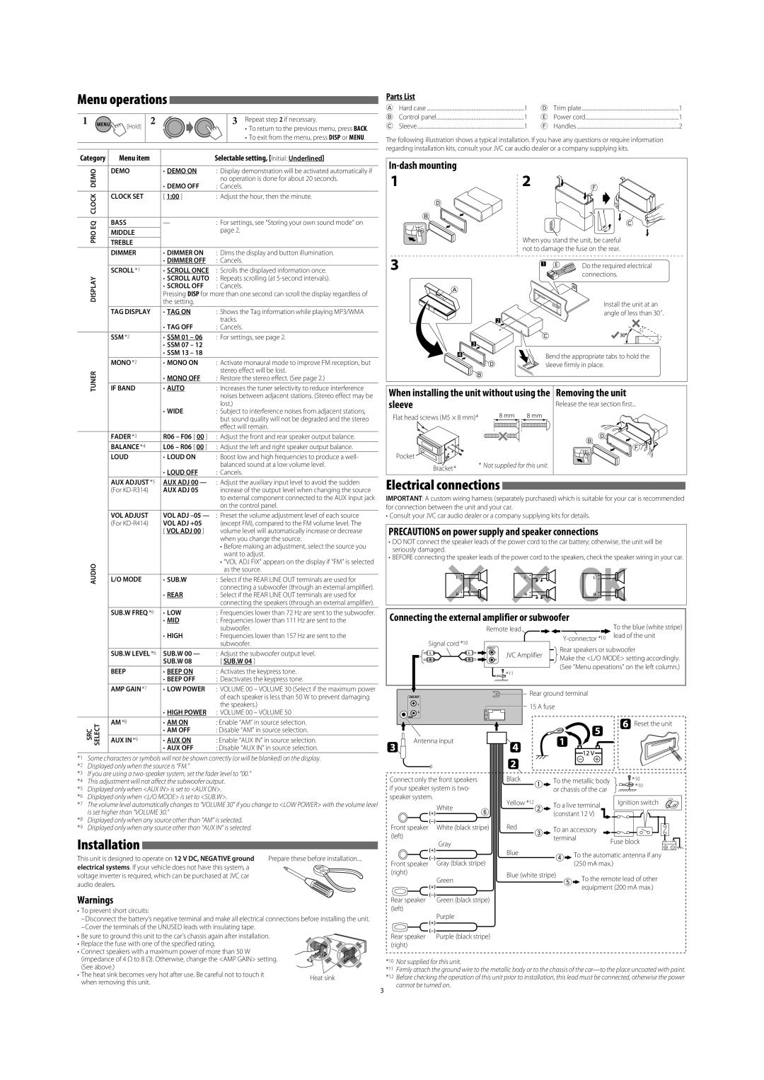
3
1 2 3 Repeat step 2 if necessary.
• To return to the previous menu, press
BACK
.
• To exit from the menu, press
DISP
or
MENU
.
Category Menu item Selectable setting, [
Initial: Underlined
]
DEMO
DEMO DEMO ON
DEMO OFF
: Display demonstration will be activated automatically if
no operation is done for about 20 seconds.
: Cancels.
CLOCK
CLOCK SET [ 1:00 ] : Adjust the hour, then the minute.
PRO EQ
BASS : For settings, see “Storing your own sound mode” on
page 2.
MIDDLE
TREBLE
DISPLAY
DIMMER DIMMER ON
DIMMER OFF
: Dims the display and button illumination.
: Cancels.
SCROLL *1SCROLL ONCE
SCROLL AUTO
SCROLL OFF
: Scrolls the displayed information once.
: Repeats scrolling (at 5-second intervals).
: Cancels.
Pressing
DISP
for more than one second can scroll the display regardless of
the setting.
TAG DISPLAY TAG ON
TAG OFF
: Shows the Tag information while playing MP3/WMA
tracks.
: Cancels.
TUNER
SSM *2 SSM 01 – 06
SSM 07 – 12
SSM 13 – 18
: For settings, see page 2.
MONO *2MONO ON
MONO OFF
: Activate monaural mode to improve FM reception, but
stereo effect will be lost.
: Restore the stereo effect. (See page 2.)
IF BAND AUTO
WIDE
: Increases the tuner selectivity to reduce interference
noises between adjacent stations. (Stereo effect may be
lost.)
: Subject to interference noises from adjacent stations,
but sound quality will not be degraded and the stereo
effect will remain.
AUDIO
FADER *3R06 – F06 [ 00 ] : Adjust the front and rear speaker output balance.
BALANCE *4L06 – R06 [ 00 ] : Adjust the left and right speaker output balance.
LOUD LOUD ON
LOUD OFF
: Boost low and high frequencies to produce a well-
balanced sound at a low volume level.
: Cancels.
AUX ADJUST *5
(For KD-R314)
AUX ADJ 00 —
AUX ADJ 05
: Adjust the auxiliary input level to avoid the sudden
increase of the output level when changing the source
to external component connected to the AUX input jack
on the control panel.
VOL ADJUST
(For KD-R414)
VOL ADJ –05 —
VOL ADJ +05
[ VOL ADJ 00 ]
: Preset the volume adjustment level of each source
(except FM), compared to the FM volume level. The
volume level will automatically increase or decrease
when you change the source.
• Before making an adjustment, select the source you
want to adjust.
• “VOL ADJ FIX” appears on the display if “FM” is selected
as the source.
L/O MODE SUB.W
REAR
: Select if the REAR LINE OUT terminals are used for
connecting a subwoofer (through an external amplifier).
: Select if the REAR LINE OUT terminals are used for
connecting the speakers (through an external amplifier).
SUB.W FREQ *6LOW
MID
HIGH
: Frequencies lower than 72 Hz are sent to the subwoofer.
: Frequencies lower than 111 Hz are sent to the
subwoofer.
: Frequencies lower than 157 Hz are sent to the
subwoofer.
SUB.W LEVEL *6SUB.W 00 —
SUB.W 08
: Adjust the subwoofer output level.
[ SUB.W 04 ]
BEEP BEEP ON
BEEP OFF
: Activates the keypress tone.
: Deactivates the keypress tone.
AMP GAIN *7
LOW POWER
HIGH POWER
: VOLUME 00 – VOLUME 30 (Select if the maximum power
of each speaker is less than 50 W to prevent damaging
the speakers.)
: VOLUME 00 – VOLUME 50
SRC
SELECT
AM *8AM ON
AM OFF
: Enable “AM” in source selection.
: Disable “AM” in source selection.
AUX IN *9AUX ON
AUX OFF
: Enable “AUX IN” in source selection.
: Disable “AUX IN” in source selection.
*1 Some characters or symbols will not be shown correctly (or will be blanked) on the display.
*2 Displayed only when the source is “FM.”
*3 If you are using a two-speaker system, set the fader level to “00.”
*4 This adjustment will not affect the subwoofer output.
*5 Displayed only when <AUX IN> is set to <AUX ON>.
*6 Displayed only when <L/O MODE> is set to <SUB.W>.
*7 The volume level automatically changes to “VOLUME 30” if you change to <LOW POWER> with the volume level
is set higher than “VOLUME 30.”
*8 Displayed only when any source other than “AM” is selected.
*9 Displayed only when any source other than “AUX IN” is selected.
Menu operations
[Hold]

Parts List

A
Hard case .................................................................................1
B
Control panel.........................................................................1
C
Sleeve .........................................................................................1
D
Trim plate .................................................................................1
E
Power cord ..............................................................................1
F
Handles .....................................................................................2
The following illustration shows a typical installation. If you have any questions or require information
regarding installation kits, consult your JVC car audio dealer or a company supplying kits.
In-dash mounting
When installing the unit without using the sleeve
Removing the unit
Release the rear section first...
Heat sink
Install the unit at an
angle of less than 30˚.
Do the required electrical
connections.
Bend the appropriate tabs to hold the
sleeve firmly in place.
When you stand the unit, be careful
not to damage the fuse on the rear.
Bracket*
Pocket
Flat head screws (M5 × 8 mm)*
* Not supplied for this unit.
Installation
This unit is designed to operate on 12 V DC, NEGATIVE ground
electrical systems. If your vehicle does not have this system, a
voltage inverter is required, which can be purchased at JVC car
audio dealers.
Prepare these before installation....
Warnings
• To prevent short circuits:
– Disconnect the battery’s negative terminal and make all electrical connections before installing the unit.
– Cover the terminals of the UNUSED leads with insulating tape.
• Be sure to ground this unit to the car’s chassis again after installation.
• Replace the fuse with one of the specified rating.
• Connect speakers with a maximum power of more than 50 W
(impedance of 4 Ω to 8 Ω). Otherwise, change the <AMP GAIN> setting.
(See above.)
• The heat sink becomes very hot after use. Be careful not to touch it
when removing this unit.
Electrical connections
IMPORTANT: A custom wiring harness (separately purchased) which is suitable for your car is recommended
for connection between the unit and your car.
• Consult your JVC car audio dealer or a company supplying kits for details.
PRECAUTIONS on power supply and speaker connections
• DO NOT connect the speaker leads of the power cord to the car battery; otherwise, the unit will be
seriously damaged.
• BEFORE connecting the speaker leads of the power cord to the speakers, check the speaker wiring in your car.
*10 Not supplied for this unit.
*11 Firmly attach the ground wire to the metallic body or to the chassis of the car—to the place uncoated with paint.
*12 Before checking the operation of this unit prior to installation, this lead must be connected, otherwise the power
cannot be turned on.
Rear ground terminal
15 A fuse
Antenna input
Reset the unit
Black
Fuse block
Ignition switch
Blue (white stripe)
Blue
Red
Yellow *12
To the metallic body
or chassis of the car
To an accessory
terminal
To a live terminal
(constant 12 V)
White
White (black stripe)
Gray
Gray (black stripe)
Green
Green (black stripe)
Purple
Purple (black stripe)
Front speaker
(left)
Front speaker
(right)
Rear speaker
(left)
Rear speaker
(right)
Signal cord *10 Y-connector *10
Remote lead To the blue (white stripe)
lead of the unit
Rear speakers or subwoofer
Make the <L/O MODE> setting accordingly.
(See “Menu operations” on the left column.)
JVC Amplifier
Connecting the external amplifier or subwoofer
*11
Connect only the front speakers
if your speaker system is two-
speaker system.
*10
*10
To the automatic antenna if any
(250 mA max.)
To the remote lead of other
equipment (200 mA max.)
EN_KD-R414_R314[UI]f.indd 3EN_KD-R414_R314[UI]f.indd 3 10/27/09 5:19:21 PM10/27/09 5:19:21 PM