![]()
![]()
![]()
![]()
![]()
![]()
![]()
![]()
![]()
![]()
![]()
![]()
![]()
![]()
![]()
![]()
![]()
![]()
![]()
![]()
![]()
![]()
![]()
![]()
![]()
![]()
![]()
![]()
![]()
![]()
![]()
![]()
![]()
![]()
![]()
![]()
![]()
![]()
![]()
![]()
![]()
![]()
![]()
![]()
![]()
![]()
![]()
![]()
![]()
![]()
![]()
![]()
![]()
![]()
![]()
![]()
![]()
![]()
![]()
![]()
![]()
![]()
![]()
![]()
![]()
![]()
![]()
![]()
![]()
![]()
![]()
![]()
![]()
![]()
![]()
![]()
![]()
![]()
![]()
![]()
![]()
![]()
![]()
![]()
![]()
![]()
![]()
![]()
![]()
![]()
![]()
![]()
![]()
![]()
![]()
![]()
![]()
![]()
![]()
![]()
![]()
![]()
![]()
![]()
![]()
![]()
![]() 5
5![]()
STEP
2
INSTALLATION
CONNECT VIDEO RECORDER TO TV
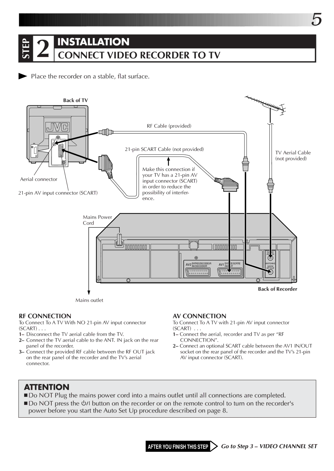
 Place the recorder on a stable, flat surface.
Back of TV
Aerial connector
Mains Power
Cord
RF Cable (provided)
Make this connection if your TV has a
AV2 ENTREE/DECODEURIN/DECODER
TV Aerial Cable (not provided)
| ENTREE |
| ANT. IN |
AV1 ENTREE/SORTIE | ANTENNE |
IN/OUT | SORTIE |
| OUT |
Mains outlet
RF CONNECTION
To Connect To A TV With NO
1– Disconnect the TV aerial cable from the TV.
2– Connect the TV aerial cable to the ANT. IN jack on the rear panel of the recorder.
3– Connect the provided RF cable between the RF OUT jack on the rear panel of the recorder and the TV’s aerial connector.
Back of Recorder
AV CONNECTION
To Connect To A TV with
1– Connect the aerial, recorder and TV as per “RF
CONNECTION”.
2– Connect an optional SCART cable between the AV1 IN/OUT socket on the rear panel of the recorder and the TV’s
ATTENTION
■Do NOT Plug the mains power cord into a mains outlet until all connections are completed.
■Do NOT press the ![]()
![]()
![]() button on the recorder or on the remote control to turn on the recorder's power before you start the Auto Set Up procedure described on page 8.
button on the recorder or on the remote control to turn on the recorder's power before you start the Auto Set Up procedure described on page 8.
AFTER YOU FINISH THIS STEP ![]() Go to Step 3 – VIDEO CHANNEL SET
Go to Step 3 – VIDEO CHANNEL SET