Installation, Operation & Maintenance | HTV/HTD/HTH SERIES | Heat Controller, Inc. |
Functional Troubleshooting
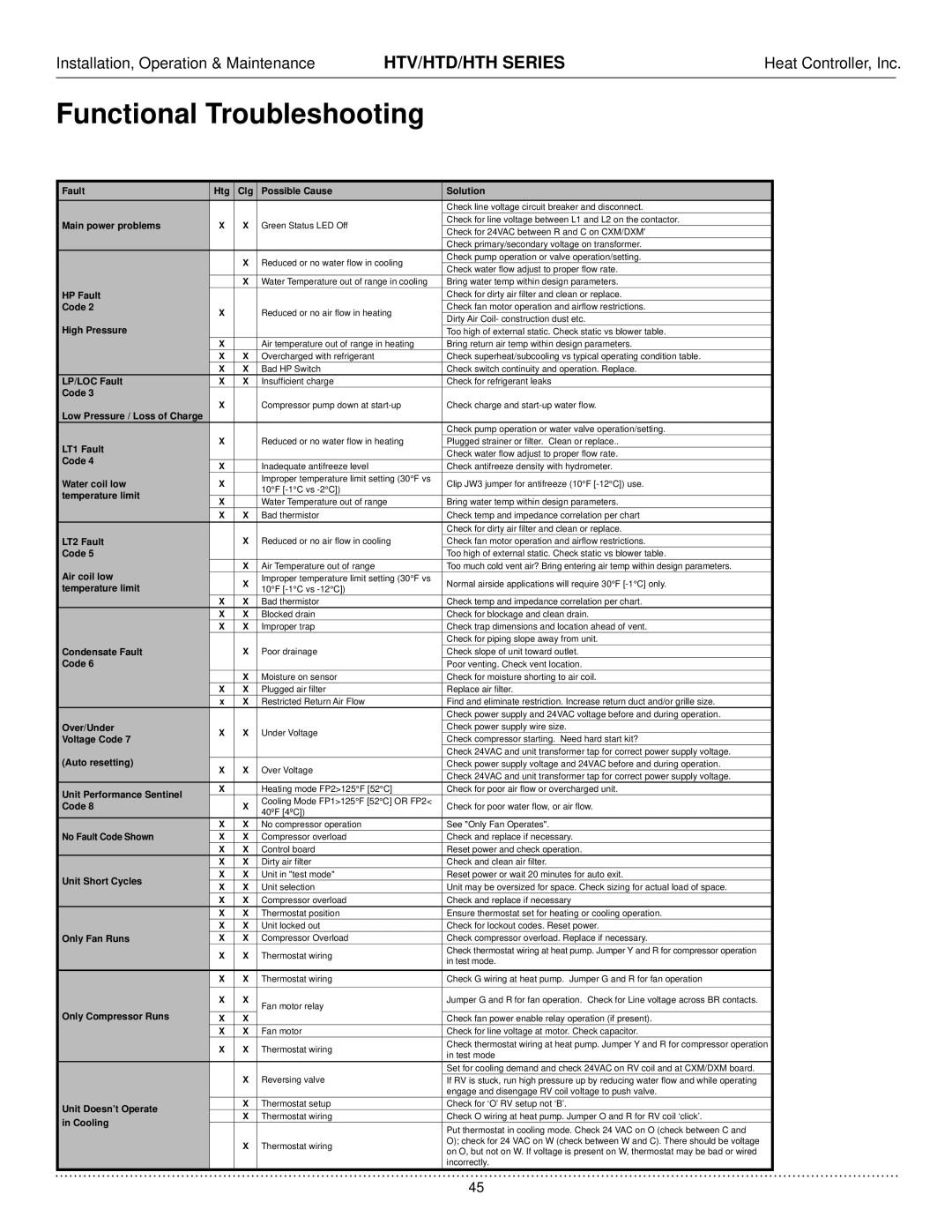
Fault | Htg | Clg | Possible Cause | Solution | |
|
|
|
| Check line voltage circuit breaker and disconnect. | |
Main power problems | X | X | Green Status LED Off | Check for line voltage between L1 and L2 on the contactor. | |
Check for 24VAC between R and C on CXM/DXM' | |||||
|
|
|
| ||
|
|
|
| Check primary/secondary voltage on transformer. | |
|
| X | Reduced or no water flow in cooling | Check pump operation or valve operation/setting. | |
|
| Check water flow adjust to proper flow rate. | |||
|
|
|
| ||
|
| X | Water Temperature out of range in cooling | Bring water temp within design parameters. | |
HP Fault |
|
|
| Check for dirty air filter and clean or replace. | |
Code 2 | X |
| Reduced or no air flow in heating | Check fan motor operation and airflow restrictions. | |
High Pressure |
| Dirty Air Coil- construction dust etc. | |||
|
|
| |||
|
|
| Too high of external static. Check static vs blower table. | ||
| X |
| Air temperature out of range in heating | Bring return air temp within design parameters. | |
| X | X | Overcharged with refrigerant | Check superheat/subcooling vs typical operating condition table. | |
| X | X | Bad HP Switch | Check switch continuity and operation. Replace. | |
LP/LOC Fault | X | X | Insufficient charge | Check for refrigerant leaks | |
Code 3 | X |
| Compressor pump down at | Check charge and | |
Low Pressure / Loss of Charge |
| ||||
|
|
|
| ||
|
|
|
| Check pump operation or water valve operation/setting. | |
LT1 Fault | X |
| Reduced or no water flow in heating | Plugged strainer or filter. Clean or replace.. | |
|
|
| Check water flow adjust to proper flow rate. | ||
Code 4 |
|
|
|
| |
X |
| Inadequate antifreeze level | Check antifreeze density with hydrometer. | ||
|
| ||||
Water coil low | X |
| Improper temperature limit setting (30°F vs | Clip JW3 jumper for antifreeze (10°F | |
| 10°F | ||||
temperature limit |
|
|
| ||
X |
| Water Temperature out of range | Bring water temp within design parameters. | ||
|
| ||||
| X | X | Bad thermistor | Check temp and impedance correlation per chart | |
|
|
|
| Check for dirty air filter and clean or replace. | |
LT2 Fault |
| X | Reduced or no air flow in cooling | Check fan motor operation and airflow restrictions. | |
Code 5 |
|
|
| Too high of external static. Check static vs blower table. | |
Air coil low |
| X | Air Temperature out of range | Too much cold vent air? Bring entering air temp within design parameters. | |
| X | Improper temperature limit setting (30°F vs | Normal airside applications will require 30°F | ||
temperature limit |
| 10°F | |||
|
|
| |||
| X | X | Bad thermistor | Check temp and impedance correlation per chart. | |
| X | X | Blocked drain | Check for blockage and clean drain. | |
| X | X | Improper trap | Check trap dimensions and location ahead of vent. | |
|
|
|
| Check for piping slope away from unit. | |
Condensate Fault |
| X | Poor drainage | Check slope of unit toward outlet. | |
Code 6 |
|
|
| Poor venting. Check vent location. | |
|
| X | Moisture on sensor | Check for moisture shorting to air coil. | |
| X | X | Plugged air filter | Replace air filter. | |
| x | X | Restricted Return Air Flow | Find and eliminate restriction. Increase return duct and/or grille size. | |
|
|
|
| Check power supply and 24VAC voltage before and during operation. | |
Over/Under | X | X | Under Voltage | Check power supply wire size. | |
Voltage Code 7 | Check compressor starting. Need hard start kit? | ||||
|
|
| |||
(Auto resetting) |
|
|
| Check 24VAC and unit transformer tap for correct power supply voltage. | |
X | X | Over Voltage | Check power supply voltage and 24VAC before and during operation. | ||
| Check 24VAC and unit transformer tap for correct power supply voltage. | ||||
|
|
|
| ||
Unit Performance Sentinel | X |
| Heating mode FP2>125°F [52°C] | Check for poor air flow or overcharged unit. | |
|
| Cooling Mode FP1>125°F [52°C] OR FP2< |
| ||
Code 8 |
| X | Check for poor water flow, or air flow. | ||
| 40ºF [4ºC]) | ||||
|
|
|
| ||
No Fault Code Shown | X | X | No compressor operation | See "Only Fan Operates". | |
X | X | Compressor overload | Check and replace if necessary. | ||
| X | X | Control board | Reset power and check operation. | |
| X | X | Dirty air filter | Check and clean air filter. | |
Unit Short Cycles | X | X | Unit in "test mode" | Reset power or wait 20 minutes for auto exit. | |
X | X | Unit selection | Unit may be oversized for space. Check sizing for actual load of space. | ||
| |||||
| X | X | Compressor overload | Check and replace if necessary | |
| X | X | Thermostat position | Ensure thermostat set for heating or cooling operation. | |
| X | X | Unit locked out | Check for lockout codes. Reset power. | |
Only Fan Runs | X | X | Compressor Overload | Check compressor overload. Replace if necessary. | |
| X | X | Thermostat wiring | Check thermostat wiring at heat pump. Jumper Y and R for compressor operation | |
| in test mode. | ||||
|
|
|
| ||
|
|
|
|
| |
| X | X | Thermostat wiring | Check G wiring at heat pump. Jumper G and R for fan operation | |
|
|
|
|
| |
| X | X | Fan motor relay | Jumper G and R for fan operation. Check for Line voltage across BR contacts. | |
Only Compressor Runs |
|
|
| ||
X | X |
| Check fan power enable relay operation (if present). | ||
| X | X | Fan motor | Check for line voltage at motor. Check capacitor. | |
| X | X | Thermostat wiring | Check thermostat wiring at heat pump. Jumper Y and R for compressor operation | |
| in test mode | ||||
|
|
|
| ||
|
|
|
| Set for cooling demand and check 24VAC on RV coil and at CXM/DXM board. | |
|
| X | Reversing valve | If RV is stuck, run high pressure up by reducing water flow and while operating | |
|
|
|
| engage and disengage RV coil voltage to push valve. | |
Unit Doesn’t Operate |
| X | Thermostat setup | Check for ‘O’ RV setup not ‘B’. | |
| X | Thermostat wiring | Check O wiring at heat pump. Jumper O and R for RV coil ‘click’. | ||
in Cooling |
| ||||
|
|
| Put thermostat in cooling mode. Check 24 VAC on O (check between C and | ||
|
|
|
| ||
|
| X | Thermostat wiring | O); check for 24 VAC on W (check between W and C). There should be voltage | |
|
| on O, but not on W. If voltage is present on W, thermostat may be bad or wired | |||
|
|
|
| ||
|
|
|
| incorrectly. |
45