Installation, Operation & Maintenance | HTV/HTD/HTH SERIES | Heat Controller, Inc. |
Water Connection Installation
External Flow Controller Mounting
The Flow Controller can be mounted beside the unit as shown in Figure 12. Review the Flow Controller installation manual for more details.
Water
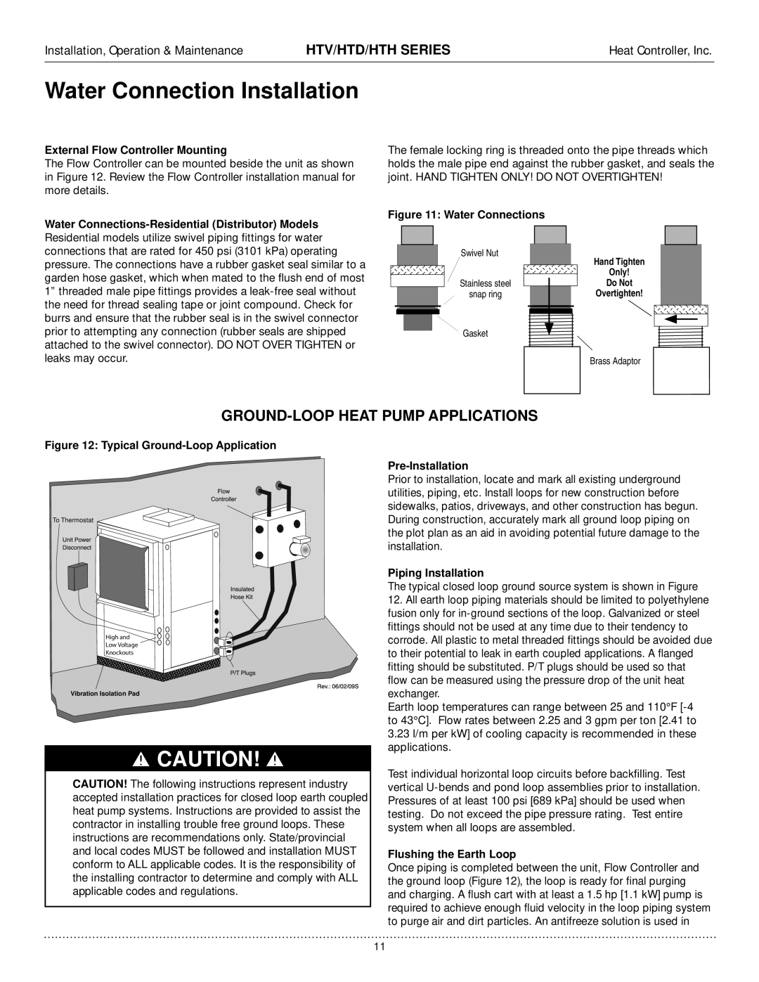
The female locking ring is threaded onto the pipe threads which holds the male pipe end against the rubber gasket, and seals the joint. HAND TIGHTEN ONLY! DO NOT OVERTIGHTEN!
Figure 11: Water Connections
Swivel Nut
| Hand Tighten |
| Only! |
Stainless steel | Do Not |
snap ring | Overtighten! |
Gasket
Brass Adaptor
GROUND-LOOP HEAT PUMP APPLICATIONS
Figure 12: Typical Ground-Loop Application
To Thermostat
High and
Low Voltage
Knockouts
Vibration Isolation Pad
CAUTION!
CAUTION! The following instructions represent industry accepted installation practices for closed loop earth coupled heat pump systems. Instructions are provided to assist the contractor in installing trouble free ground loops. These instructions are recommendations only. State/provincial and local codes MUST be followed and installation MUST conform to ALL applicable codes. It is the responsibility of the installing contractor to determine and comply with ALL applicable codes and regulations.
Pre-Installation
Prior to installation, locate and mark all existing underground utilities, piping, etc. Install loops for new construction before sidewalks, patios, driveways, and other construction has begun. During construction, accurately mark all ground loop piping on the plot plan as an aid in avoiding potential future damage to the installation.
Piping Installation
The typical closed loop ground source system is shown in Figure
12.All earth loop piping materials should be limited to polyethylene fusion only for
Earth loop temperatures can range between 25 and 110°F
Test individual horizontal loop circuits before backfilling. Test vertical
Flushing the Earth Loop
Once piping is completed between the unit, Flow Controller and the ground loop (Figure 12), the loop is ready for final purging and charging. A flush cart with at least a 1.5 hp [1.1 kW] pump is required to achieve enough fluid velocity in the loop piping system to purge air and dirt particles. An antifreeze solution is used in
11