Installation, Operation & Maintenance | HTV/HTD/HTH SERIES | Heat Controller, Inc. |
Electrical - Low Voltage Wiring
Accessory Connections
A terminal paralleling the compressor contactor coil has been provided on the CXM control. Terminal “A” is designed to control accessory devices, such as water valves. Note: This terminal should be used only with 24 Volt signals and not line voltage. Terminal “A” is energized with the compressor contactor. See Figure 20 or the specific unit wiring diagram for details.
Figure 20: Accessory Wiring
Water Solenoid Valves
An external solenoid valve(s) should be used on ground water installations to shut off flow to the unit when the compressor is not operating. A slow closing valve may be required to help reduce water hammer. Figure 20 shows typical wiring for a 24VAC external solenoid valve. Figures 21 and 22 illustrate typical slow closing water control valve wiring for Taco 500 series (Manufacturer P/N AVM...) and Taco SBV series valves. Slow closing valves take approximately 60 seconds to open (very little water will flow before 45 seconds). Once fully open, an end switch allows the compressor to be energized. Only relay or triac based electronic thermostats should be used with slow closing valves. When wired as shown, the slow closing valve will operate properly with the following notations:
1.The valve will remain open during a unit lockout.
2.The valve will draw approximately
Two-stage Units
HT
Figure 23 illustrates piping for two-stage solenoid valves. Review figures 20-22 for wiring of stage one valve. Stage two valve should be wired between terminal “Y2” (ECM board) and terminal “C.”
Note: When EWT is below 50°F [10°C], a minimum of 2 gpm per ton (2.6 l/m per kW) is required.
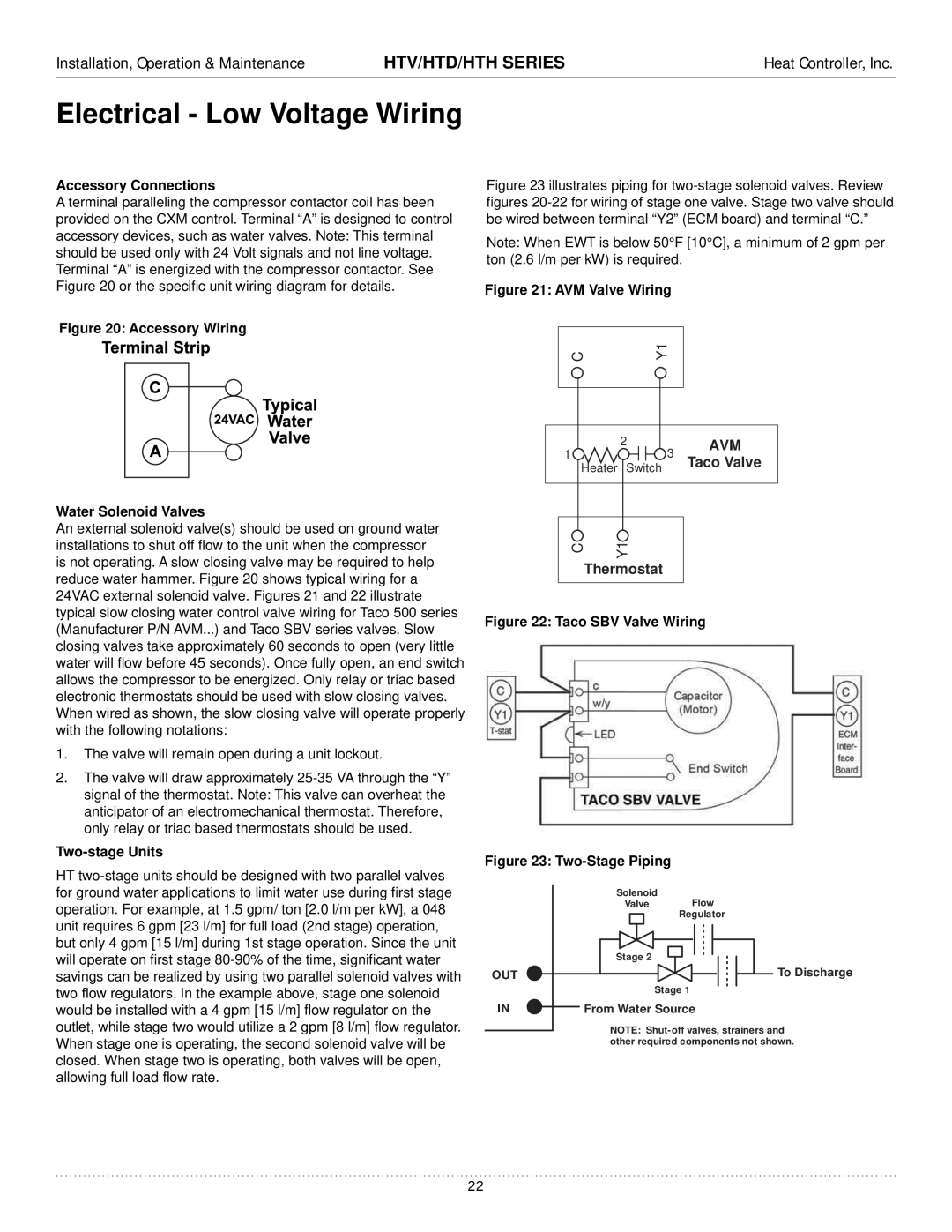
Figure 21: AVM Valve Wiring
C | Y1 | ||
|
|
|
|
|
|
|
|
2 | 3 | AVM |
1 | Taco Valve | |
Heater Switch |
|
|
C | Y1 |
Thermostat
Figure 22: Taco SBV Valve Wiring
Figure 23: |
|
Solenoid | Flow |
Valve | |
| Regulator |
Stage 2 |
|
OUT | To Discharge |
Stage 1 | |
IN |
| From Water Source |
|
NOTE:
22