Installation, Operation & Maintenance | HTV/HTD/HTH SERIES | Heat Controller, Inc. |
Model Breakdown
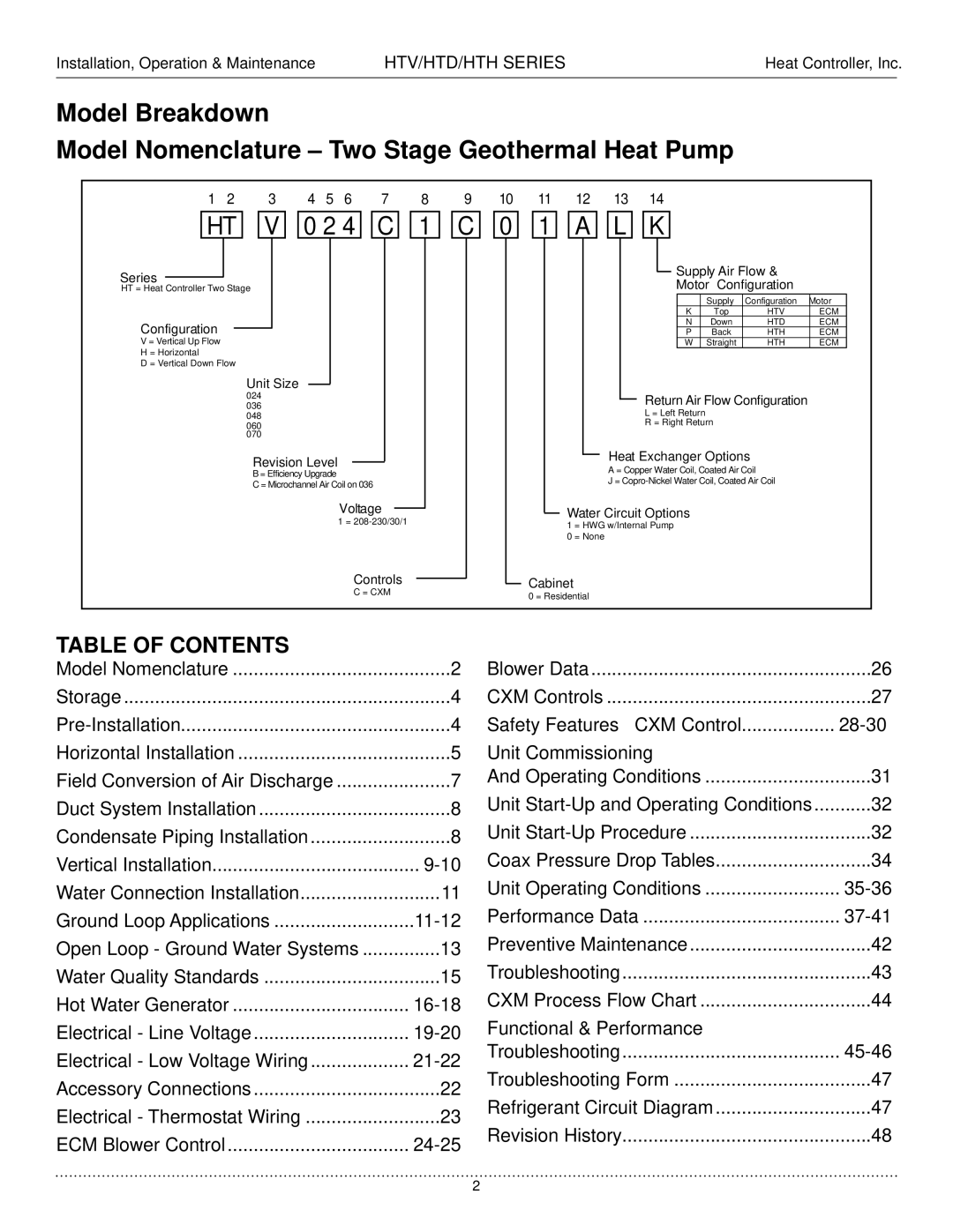
Model Nomenclature – Two Stage Geothermal Heat Pump
| 1 |
| 2 |
|
| 3 |
|
| 4 | 5 | 6 | 7 |
|
| 9 | 10 |
| 11 |
| 12 |
|
| 13 |
|
| 14 |
|
|
|
|
|
|
|
|
|
|
| |||||||||||||||||||||
|
|
|
|
|
|
|
|
|
|
|
|
|
|
|
|
|
|
|
|
|
|
|
|
|
|
|
|
|
|
|
|
|
|
|
|
|
|
|
| |||||||||||||||||||
|
|
| HT |
| V |
| 0 2 4 |
| C |
| 1 |
| C |
| 0 |
| 1 |
| A |
| L |
| K |
|
|
|
|
|
|
|
|
|
| |||||||||||||||||||||||||
| Series |
|
|
|
|
|
|
|
|
|
|
|
|
|
|
|
|
|
|
|
|
|
|
|
|
|
|
|
|
|
|
|
|
|
|
|
|
|
|
|
|
|
|
|
|
|
|
| Supply Air Flow & |
|
|
| ||||||
|
|
|
|
|
|
|
|
|
|
|
|
|
|
|
|
|
|
|
|
|
|
|
|
|
|
|
|
|
|
|
|
|
|
|
|
|
|
|
|
|
|
|
|
|
|
|
|
|
|
| ||||||||
|
|
|
|
|
|
|
|
|
|
|
|
|
|
|
|
|
|
|
|
|
|
|
|
|
|
|
|
|
|
|
|
|
|
|
|
|
|
|
|
|
|
|
|
|
|
| Motor Configuration |
|
|
| ||||||||
| HT = Heat Controller Two Stage |
|
|
|
|
|
|
|
|
|
|
|
|
|
|
|
|
|
|
|
|
|
|
|
|
|
|
|
|
|
|
|
|
|
|
|
|
|
|
|
|
|
|
| ||||||||||||||
|
|
|
|
|
|
|
|
|
|
|
|
|
|
|
|
|
|
|
|
|
|
|
|
|
|
|
|
|
|
|
|
|
|
|
|
|
|
|
|
|
|
|
|
|
|
|
|
|
|
|
| Supply |
| Configuration |
| Motor |
|
|
|
|
|
|
|
|
|
|
|
|
|
|
|
|
|
|
|
|
|
|
|
|
|
|
|
|
|
|
|
|
|
|
|
|
|
|
|
|
|
|
|
|
|
|
|
|
|
|
|
| K |
| Top |
| HTV |
| ECM |
|
|
| Configuration |
|
|
|
|
|
|
|
|
|
|
|
|
|
|
|
|
|
|
|
|
|
|
|
|
|
|
|
|
|
|
|
|
|
|
|
|
|
|
|
|
|
|
|
|
| N |
| Down |
| HTD |
| ECM |
|
| |||
|
|
|
|
|
|
|
|
|
|
|
|
|
|
|
|
|
|
|
|
|
|
|
|
|
|
|
|
|
|
|
|
|
|
|
|
|
|
|
|
|
|
|
|
|
| P |
| Back |
| HTH |
| ECM |
|
| ||||
| V = Vertical Up Flow |
|
|
|
|
|
|
|
|
|
|
|
|
|
|
|
|
|
|
|
|
|
|
|
|
|
|
|
|
|
|
|
|
|
|
|
|
|
|
|
|
|
|
|
|
| W |
| Straight |
| HTH |
| ECM |
|
| |||
| H = Horizontal |
|
|
|
|
|
|
|
|
|
|
|
|
|
|
|
|
|
|
|
|
|
|
|
|
|
|
|
|
|
|
|
|
|
|
|
|
|
|
|
|
|
|
|
|
|
|
|
|
|
|
|
|
|
| |||
| D = Vertical Down Flow |
|
|
|
|
|
|
|
|
|
|
|
|
|
|
|
|
|
|
|
|
|
|
|
|
|
|
|
|
|
|
|
|
|
|
|
|
|
|
|
|
|
|
|
|
|
|
|
|
|
| |||||||
|
|
|
|
|
|
| Unit Size |
|
|
|
|
|
|
|
|
|
|
|
|
|
|
|
|
|
|
|
|
|
|
|
|
|
|
|
|
|
|
|
|
|
|
|
|
|
|
|
|
|
|
|
|
|
| |||||
|
|
|
|
|
|
|
|
|
|
|
|
|
|
|
|
|
|
|
|
|
|
|
|
|
|
|
|
|
|
|
|
|
|
|
|
|
|
|
|
|
|
|
|
|
|
|
|
|
|
| ||||||||
|
|
|
|
| 024 |
|
|
|
|
|
|
|
|
|
|
|
|
|
|
|
|
|
|
|
|
|
|
|
|
|
|
|
|
|
|
|
|
|
|
|
|
| Return Air Flow Configuration |
| ||||||||||||||
|
|
|
|
| 036 |
|
|
|
|
|
|
|
|
|
|
|
|
|
|
|
|
|
|
|
|
|
|
|
|
|
|
|
|
|
|
|
|
|
|
|
|
|
| |||||||||||||||
|
|
|
|
| 048 |
|
|
|
|
|
|
|
|
|
|
|
|
|
|
|
|
|
|
|
|
|
|
|
|
|
|
|
|
|
|
|
|
|
|
|
|
| L = Left Return |
|
|
|
|
|
|
| ||||||||
|
|
|
|
|
|
|
|
|
|
|
|
|
|
|
|
|
|
|
|
|
|
|
|
|
|
|
|
|
|
|
|
|
|
|
|
|
|
|
|
|
| R = Right Return |
|
|
|
|
| |||||||||||
|
|
|
|
| 060 |
|
|
|
|
|
|
|
|
|
|
|
|
|
|
|
|
|
|
|
|
|
|
|
|
|
|
|
|
|
|
|
|
|
|
|
|
|
|
|
|
|
| |||||||||||
|
|
|
|
| 070 |
|
|
|
|
|
|
|
|
|
|
|
|
|
|
|
|
|
|
|
|
|
|
|
|
|
|
|
|
|
|
|
|
|
|
|
|
|
|
|
|
|
|
|
|
|
|
|
|
|
| |||
|
|
|
|
|
|
| Revision Level |
|
|
|
|
|
|
|
|
|
|
|
|
|
|
|
|
|
|
|
|
|
|
|
|
| Heat Exchanger Options |
|
|
| ||||||||||||||||||||||
|
|
|
|
|
|
|
|
|
|
|
|
|
|
|
|
|
|
|
|
|
|
|
|
|
|
|
|
|
|
|
|
|
|
| ||||||||||||||||||||||||
|
|
|
|
|
|
|
|
|
|
|
|
|
|
|
|
|
|
|
|
|
|
|
|
|
|
|
|
|
|
|
| A = Copper Water Coil, Coated Air Coil |
|
|
| |||||||||||||||||||||||
|
|
|
|
|
|
| B = Efficiency Upgrade |
|
|
|
|
|
|
|
|
|
|
|
|
|
|
|
|
|
|
|
|
|
|
|
|
|
|
|
|
| ||||||||||||||||||||||
|
|
|
|
|
|
|
|
|
|
|
|
|
|
|
|
|
|
|
|
|
|
|
|
|
|
|
|
|
|
|
|
| J = |
|
|
| ||||||||||||||||||||||
|
|
|
|
|
|
| C = Microchannel Air Coil on 036 |
|
|
|
|
|
|
|
|
|
|
|
|
|
|
|
|
|
|
|
|
|
| |||||||||||||||||||||||||||||
|
|
|
|
|
|
|
|
|
|
|
|
|
|
|
|
|
|
|
|
|
|
|
|
|
|
|
|
|
|
|
|
|
|
|
|
|
|
|
|
|
|
| ||||||||||||||||
|
|
|
|
|
|
|
|
|
|
|
|
|
|
|
| Voltage |
|
|
|
|
|
|
|
|
|
|
|
|
|
|
|
| Water Circuit Options |
|
|
|
|
|
|
| ||||||||||||||||||
|
|
|
|
|
|
|
|
|
|
|
|
|
|
|
|
|
|
|
|
|
|
|
|
|
|
|
|
|
|
|
|
|
|
|
|
|
|
| ||||||||||||||||||||
|
|
|
|
|
|
|
|
|
|
|
|
|
|
|
| 1 = |
|
|
|
|
|
|
|
|
|
|
|
|
|
|
|
|
|
|
|
|
| |||||||||||||||||||||
|
|
|
|
|
|
|
|
|
|
|
|
|
|
|
|
|
|
|
|
|
|
|
|
|
|
|
|
|
| 1 = HWG w/Internal Pump |
|
|
|
|
|
|
| |||||||||||||||||||||
|
|
|
|
|
|
|
|
|
|
|
|
|
|
|
|
|
|
|
|
|
|
|
|
|
|
|
|
|
|
|
|
|
|
|
|
|
|
|
|
|
|
|
| |||||||||||||||
|
|
|
|
|
|
|
|
|
|
|
|
|
|
|
|
|
|
|
|
|
|
|
|
|
|
|
|
|
|
|
|
|
|
|
|
| 0 = None |
|
|
|
|
|
|
|
|
|
|
|
|
|
|
|
|
| ||||
|
|
|
|
|
|
|
|
|
|
|
|
|
|
|
|
| Controls |
|
|
|
|
|
|
|
|
|
| Cabinet |
|
|
|
|
|
|
|
|
|
|
|
|
|
|
|
|
| |||||||||||||
|
|
|
|
|
|
|
|
|
|
|
|
|
|
|
|
|
|
|
|
|
|
|
|
|
|
|
|
|
|
|
|
|
|
|
|
|
|
|
|
|
|
|
| |||||||||||||||
|
|
|
|
|
|
|
|
|
|
|
|
|
|
|
|
|
|
|
|
|
|
|
|
|
|
|
|
|
|
|
|
|
|
|
|
|
|
|
|
|
|
|
| |||||||||||||||
|
|
|
|
|
|
|
|
|
|
|
|
|
|
|
|
| C = CXM |
|
|
|
|
|
|
|
|
|
| 0 = Residential |
|
|
|
|
|
|
|
|
|
|
|
|
|
|
|
|
| |||||||||||||
|
|
|
|
|
|
|
|
|
|
|
|
|
|
|
|
|
|
|
|
|
|
|
|
|
|
|
|
|
|
|
|
|
|
|
|
|
|
|
|
|
|
|
|
|
|
|
|
|
| |||||||||
|
|
|
|
|
|
|
|
|
|
|
|
|
|
|
|
|
|
|
|
|
|
|
|
|
|
|
|
|
|
|
|
|
|
|
|
|
|
|
|
|
|
|
|
|
|
|
| |||||||||||
TABLE OF CONTENTS |
|
|
|
|
|
|
|
|
|
|
|
|
|
|
|
|
|
|
|
|
|
|
|
|
|
|
|
|
|
|
|
|
|
|
|
|
|
|
|
|
|
|
|
|
|
| ||||||||||||
Model Nomenclature |
|
|
|
|
|
|
|
|
|
|
|
|
| 2 |
| Blower Data |
|
|
|
|
|
|
|
|
|
|
|
|
|
| 26 | |||||||||||||||||||||||||||
Storage |
|
|
|
|
|
|
|
|
|
|
|
|
|
|
|
|
| 4 |
| CXM Controls |
|
|
|
|
|
|
|
|
|
|
|
|
|
| 27 | |||||||||||||||||||||||
|
|
|
|
|
|
|
|
|
|
|
|
|
|
|
|
| 4 |
| Safety Features – CXM Control | .................. |
| |||||||||||||||||||||||||||||||||||||
Horizontal Installation |
|
|
|
|
|
|
|
|
|
|
|
|
| 5 |
| Unit Commissioning |
|
|
|
|
|
|
| |||||||||||||||||||||||||||||||||||
Field Conversion of Air Discharge |
|
|
|
|
|
| 7 |
| And Operating Conditions |
|
|
| 31 | |||||||||||||||||||||||||||||||||||||||||||||
Duct System Installation |
|
|
|
|
|
|
|
|
|
|
|
|
| 8 |
| Unit | ...........32 | |||||||||||||||||||||||||||||||||||||||||
Condensate Piping Installation |
|
|
|
|
|
|
|
| 8 |
| Unit |
|
|
| 32 | |||||||||||||||||||||||||||||||||||||||||||
Vertical Installation |
|
|
|
|
|
|
|
|
|
|
|
|
|
|
|
|
|
| Coax Pressure Drop Tables |
| 34 | |||||||||||||||||||||||||||||||||||||
Water Connection Installation |
|
|
|
|
|
|
|
|
|
| 11 |
| Unit Operating Conditions |
|
|
| ||||||||||||||||||||||||||||||||||||||||||
Ground Loop Applications |
|
|
|
|
|
|
|
|
|
|
| Performance Data | ...................................... |
|
|
|
|
|
|
|
|
| ||||||||||||||||||||||||||||||||||||
Open Loop - Ground Water Systems | 13 |
| Preventive Maintenance |
|
|
| 42 | |||||||||||||||||||||||||||||||||||||||||||||||||||
Water Quality Standards | .................................. |
|
|
|
|
|
|
|
|
|
|
|
|
| 15 |
| Troubleshooting |
|
|
|
|
|
|
|
|
|
| 43 | ||||||||||||||||||||||||||||||
Hot Water Generator |
|
|
|
|
|
|
|
|
|
|
|
|
|
| CXM Process Flow Chart |
|
|
| 44 | |||||||||||||||||||||||||||||||||||||||
Electrical - Line Voltage |
|
|
|
|
|
|
|
|
|
|
|
|
|
| Functional & Performance |
|
|
|
|
|
|
| ||||||||||||||||||||||||||||||||||||
Electrical - Low Voltage Wiring |
|
|
|
|
|
|
|
|
|
| Troubleshooting |
|
|
|
|
|
|
|
|
|
| |||||||||||||||||||||||||||||||||||||
|
|
|
|
|
|
|
|
| Troubleshooting Form |
|
|
| 47 | |||||||||||||||||||||||||||||||||||||||||||||
Accessory Connections |
|
|
|
|
|
|
|
|
|
|
|
|
| 22 |
|
|
|
| ||||||||||||||||||||||||||||||||||||||||
|
|
|
|
|
|
|
|
|
|
|
|
|
| Refrigerant Circuit Diagram |
| 47 | ||||||||||||||||||||||||||||||||||||||||||
Electrical - Thermostat Wiring |
|
|
|
|
|
|
|
|
|
| 23 |
|
| |||||||||||||||||||||||||||||||||||||||||||||
|
|
|
|
|
|
|
|
|
|
| Revision History |
|
|
|
|
|
|
|
|
|
| 48 | ||||||||||||||||||||||||||||||||||||
ECM Blower Control |
|
|
|
|
|
|
|
|
|
|
|
|
|
|
|
|
|
|
|
|
|
|
|
|
|
|
|
|
| |||||||||||||||||||||||||||||
................................... |
|
|
|
|
|
|
|
|
|
|
|
|
|
|
|
|
|
|
|
|
|
|
|
|
|
|
|
|
|
|
|
|
|
|
|
|
|
|
|
|
|
|
|
|
|
|
| |||||||||||
2