KD-G498
Installation/Connection Manual
1004DTSMDTJEIN | |
[UH] | EN, TH |
ENGLISH |
|
| ‰∑¬ |
|
|
This unit is designed to operate on 12 V DC, NEGATIVE ground electrical systems. If your |
|
| |||
vehicle does not have this system, a voltage inverter is required, which can be purchased at |
| ||||
JVC car audio dealers. |
|
|
| ||
Parts list for installation and connection |
|
| √“¬°“√ |
| |
The following parts are provided for this unit. |
|
|
| ||
After checking them, please set them correctly. |
|
|
|
|
|
A / B | C | D |
| E | F |
Hard case/Control panel | Sleeve | Trim plate |
| Power cord | Washer (ø5) |
| ª≈Õ°ÀÿÈ¡ |
| “¬‡§‡∫‘≈°”≈ß— | ||
G | H | I | J | K | L |
|
Lock nut (M5) | Mounting bolt (M5 x 20 mm) | Rubber cushion | Handles | Remote controller | Battery |
|
πÕµ≈ÁÕ§ (M5) | ≈°µ‘— ¥ (M5 x 20 ¡‘≈≈‘‡¡µ√) | √’‚¡µ§Õπ‚∑√≈ | ·∫µ‡µÕ√’Ë | CR2025 |
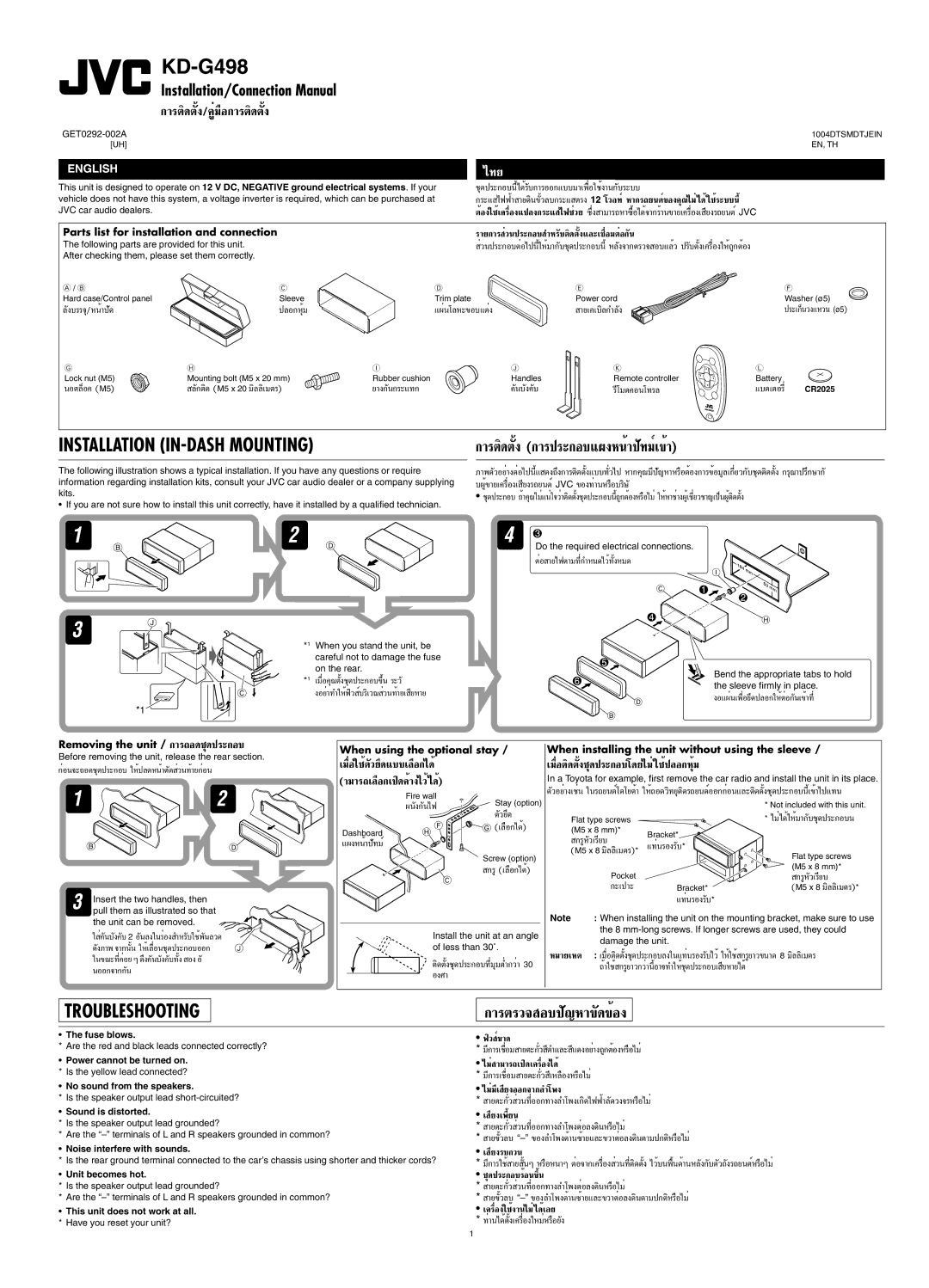
INSTALLATION | °“√µ‘¥µßÈ— |
The following illustration shows a typical installation. If you have any questions or require information regarding installation kits, consult your JVC car audio dealer or a company supplying kits.
• If you are not sure how to install this unit correctly, have it installed by a qualified technician.
*1 When you stand the unit, be careful not to damage the fuse on the rear.
*1 ‡¡◊ËÕ§ÿ≥µß™ÿ—È ¥ª√–°Õ∫¢÷Èπ √–«—
ßլ˓∑”„ÀÈø‘« ∫√‘‡«≥Ï «π∑È“¬‡Ë ¬À“¬’
¿“浫լ˓ߵËÕ‰ªπ’È·—
•
Do the required electrical connections.
µËÕ “¬‰øµ“¡∑’Ë°”À𥉫È∑ßÀ¡È— ¥
Bend the appropriate tabs to hold the sleeve firmly in place.
ßÕ·ºËπ‡æ◊ËÕ¬÷¥ª≈Õ°„ÀȵËÕ°π‡— ¢È“∑’Ë
Removing the unit /
Before removing the unit, release the rear section.
°ËÕπ®–∂Õ¥™ÿ¥ª√–°Õ∫ „ÀȪ≈¥ÀπÈ“µ¥— «π∑È“¬°ËÕπË
Insert the two handles, then pull them as illustrated so that the unit can be removed.
„
When using the optional stay /
‡¡◊ËÕ„™Èµ«¬÷— ¥·∫∫‡≈◊Õ°‰¥È
(“¡“√∂‡≈◊Õ°‡ª‘¥§È“߉«È‰¥È)
Fire wall
Stay (option) | ||
µ«¬÷— ¥ | ||
| ||
Dashboard | (‡≈◊Õ°‰¥È) | |
| ||
·ºßÀπÈ“ª∑¡Ï— |
| |
| Screw (option) |
°√Ÿ(‡≈◊Õ°‰¥È)
Install the unit at an angle of less than 30˚.
µ‘¥µß™ÿÈ—
When installing the unit without using the sleeve /
‡¡◊ËÕµ‘¥µß™ÿÈ— ¥ª√–°Õ∫‚¥¬‰¡Ë„™Èª≈Õ°ÀÿÈ¡
In a Toyota for example, first remove the car radio and install the unit in its place.
µ«Õ¬Ë“߇™Ëπ— „π√∂¬πµÏ‚µ‚¬µÈ“
|
|
| * Not included with this unit. | ||
| Flat type screws |
| * ‰¡Ë‰¥È„ÀÈ¡“°∫™ÿ— |
| |
| (M5 x 8 mm)* | Bracket* |
|
|
|
| °√ŸÀ«‡√’¬∫— |
|
|
| |
|
|
|
| ||
| (M5 x 8 ¡‘≈≈‘‡¡µ√)* | Flat type screws |
| ||
|
|
| |||
|
|
|
| ||
|
|
| (M5 x 8 mm)* |
| |
| Bracket* | °√ŸÀ«‡√’¬∫— | * | ||
| M5 x 8 | ¡‘≈≈‘‡¡µ√) | |||
|
| ( |
| ||
|
|
|
|
| |
Note | : When installing the unit on the mounting bracket, make sure to use | ||||
| the 8 |
| |||
| damage the unit. |
|
|
| |
À¡“¬‡Àµ :
TROUBLESHOOTING
°“√µ√«® Õ∫ª≠À“— ¢¥—¢ÈÕß
•The fuse blows.
* Are the red and black leads connected correctly?
•Power cannot be turned on. * Is the yellow lead connected?
•No sound from the speakers.
* Is the speaker output lead
•Sound is distorted.
*Is the speaker output lead grounded?
*Are the
•Noise interfere with sounds.
* Is the rear ground terminal connected to the car’s chassis using shorter and thicker cords?
•Unit becomes hot.
*Is the speaker output lead grounded?
*Are the
•This unit does not work at all. * Have you reset your unit?
•ø‘« ¢Ï“¥
*¡’°“√‡™◊ËÕ¡
•‰¡Ë“¡“√∂‡ª‘¥‡§√◊ËÕ߉¥È
*¡’°“√‡™◊ËÕ¡
•‰¡Ë¡’‡ ¬ßÕÕ°®“°≈”‚æß’
*
•‡ ¬ß‡æ’Ȭπ’
*
*“¬¢«≈∫È—
•‡ ¬ß√∫°«π’
*¡’°“√„™È“¬ πÊÈ— À√◊ÕÀπ“Ê µËÕ®“°‡§√◊ËÕß «π∑’˵‘Ë ¥µßÈ—
•
*
*“¬¢«≈∫È—
•‡§√◊ËÕß„™Èß“π‰¡Ë‰¥È‡≈¬
*
1