Pin

Symbol

I/O

Descroption

No

17

TMAX

O

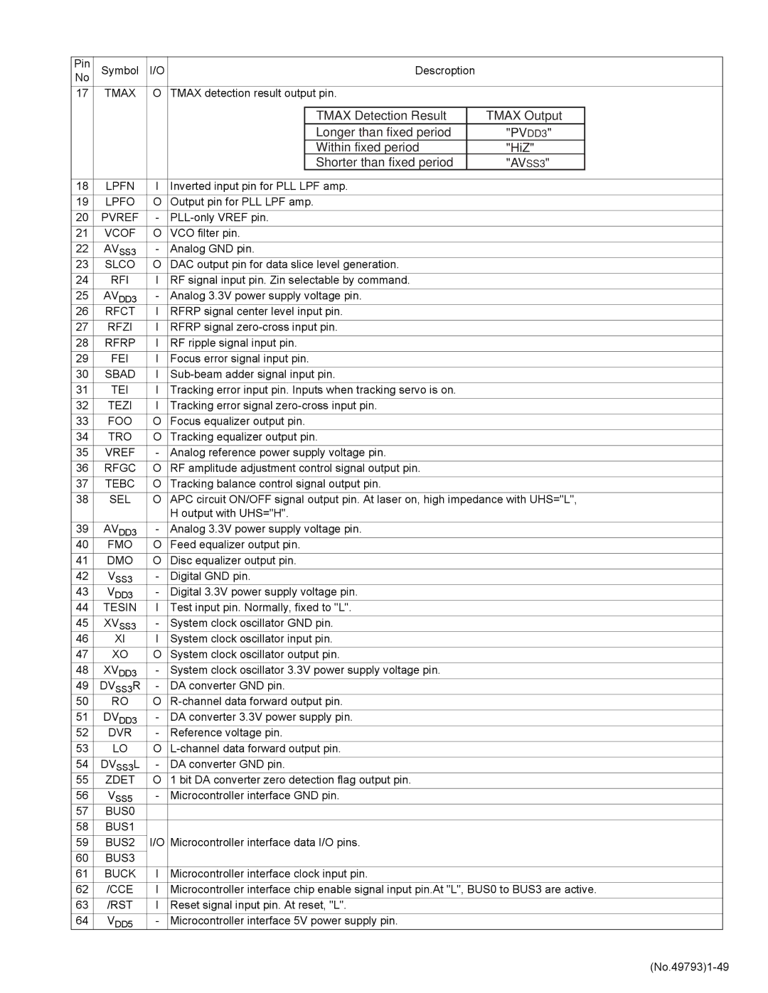
TMAX detection result output pin.


TMAX Detection Result

TMAX Output


Longer than fixed period

"PVDD3"


Within fixed period

"HiZ"


Shorter than fixed period

"AVSS3"


18

LPFN

I

Inverted input pin for PLL LPF amp.


19

LPFO

O

Output pin for PLL LPF amp.


20

PVREF

-

PLL-only VREF pin.


21

VCOF

O

VCO filter pin.


22

AVSS3

-

Analog GND pin.


23

SLCO

O

DAC output pin for data slice level generation.


24

RFI

I

RF signal input pin. Zin selectable by command.


25

AVDD3

-

Analog 3.3V power supply voltage pin.


26

RFCT

I

RFRP signal center level input pin.


27

RFZI

I

RFRP signal zero-cross input pin.


28

RFRP

I

RF ripple signal input pin.


29

FEI

I

Focus error signal input pin.


30

SBAD

I

Sub-beam adder signal input pin.


31

TEI

I

Tracking error input pin. Inputs when tracking servo is on.


32

TEZI

I

Tracking error signal zero-cross input pin.


33

FOO

O

Focus equalizer output pin.


34

TRO

O

Tracking equalizer output pin.


35

VREF

-

Analog reference power supply voltage pin.


36

RFGC

O

RF amplitude adjustment control signal output pin.


37

TEBC

O

Tracking balance control signal output pin.


38

SEL

O

APC circuit ON/OFF signal output pin. At laser on, high impedance with UHS="L",


H output with UHS="H".


39

AVDD3

-

Analog 3.3V power supply voltage pin.


40

FMO

O

Feed equalizer output pin.


41

DMO

O

Disc equalizer output pin.


42

VSS3

-

Digital GND pin.


43

VDD3

-

Digital 3.3V power supply voltage pin.


44

TESIN

I

Test input pin. Normally, fixed to "L".


45

XVSS3

-

System clock oscillator GND pin.


46

XI

I

System clock oscillator input pin.


47

XO

O

System clock oscillator output pin.


48

XVDD3

-

System clock oscillator 3.3V power supply voltage pin.


49

DVSS3R

-

DA converter GND pin.


50

RO

O

R-channel data forward output pin.


51

DVDD3

-

DA converter 3.3V power supply pin.


52

DVR

-

Reference voltage pin.


53

LO

O

L-channel data forward output pin.


54

DVSS3L

-

DA converter GND pin.


55

ZDET

O

1 bit DA converter zero detection flag output pin.


56

VSS5

-

Microcontroller interface GND pin.


57

BUS0


58

BUS1


59

BUS2

I/O Microcontroller interface data I/O pins.


60

BUS3


61

BUCK

I

Microcontroller interface clock input pin.


62

/CCE

I

Microcontroller interface chip enable signal input pin.At "L", BUS0 to BUS3 are active.

63

/RST

I

Reset signal input pin. At reset, "L".


64

VDD5

-

Microcontroller interface 5V power supply pin.


(No.49793)1-49

Page 19
Image 19
JVC KD-LX555R service manual PVDD3, AVSS3

KD-LX555R specifications

The JVC KD-LX555R is a feature-rich car stereo receiver that combines cutting-edge technologies with an impressive array of functionalities, making it a popular choice among car audio enthusiasts. One of the standout features of the KD-LX555R is its compatibility with various audio playback formats, including MP3, WMA, and WAV files. This versatility allows users to enjoy their favorite music from different sources without compromising on sound quality.

Equipped with a front AUX input and a USB port, the KD-LX555R facilitates convenient connectivity for external devices like smartphones and USB drives. This feature enables users to access their digital music collections seamlessly while driving. Additionally, the unit's Bluetooth capability allows for hands-free calling and wireless audio streaming, enhancing convenience and safety by minimizing distractions while driving.

The receiver boasts a sleek and modern design, featuring an easy-to-read LCD display and user-friendly controls. The customizable illumination options enable users to match the display color to their vehicle’s interior, adding a personalized touch. Its ergonomic layout ensures that drivers can adjust settings and navigate menus with minimal effort, allowing for a safer driving experience.

Sound quality is a paramount consideration for JVC, and the KD-LX555R does not disappoint. It features a powerful MOSFET amplifier, delivering robust audio performance with impressive clarity and depth across all frequencies. The inclusion of a 3-band parametric equalizer also allows users to fine-tune the audio output according to their preferences and the acoustics of their car.

For those who desire even more control over their sound, the KD-LX555R supports additional amplifiers and subwoofers through its preamp outputs. This feature empowers users to easily upgrade their sound systems and achieve the desired audio experience. Moreover, the receiver integrates seamlessly with smartphones, enabling features like music control through voice commands.

In summary, the JVC KD-LX555R is a comprehensive car audio solution that emphasizes connectivity, sound quality, and user convenience. With its modern features, robust performance, and customizable options, it caters to a wide range of audio preferences, making it a worthy addition to any car. Whether enjoying favorite tracks or making hands-free calls, the KD-LX555R delivers an exceptional in-car experience that combines technology with practicality.