
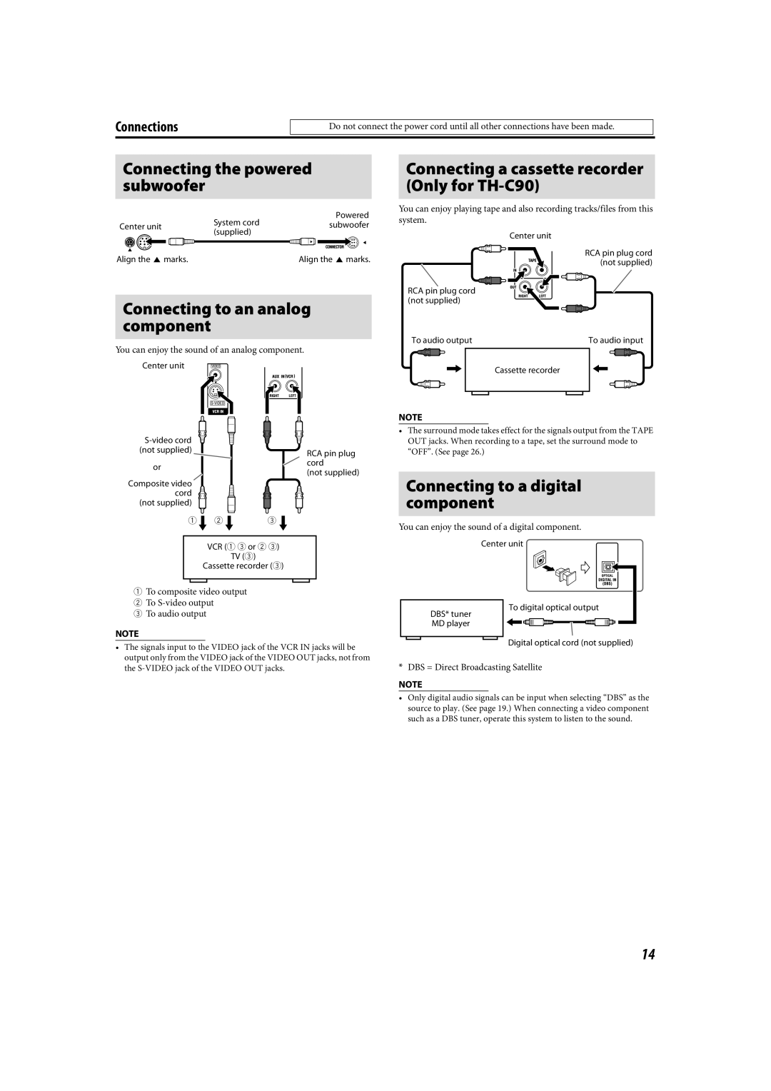
LVT1504-005B specifications
The JVC LVT1504-005B is a cutting-edge audio speaker set that stands out in the competitive landscape of home audio technology. Designed to elevate your listening experience, it combines advanced engineering and sleek aesthetics to deliver outstanding sound quality.One of the most notable features of the JVC LVT1504-005B is its sophisticated sound reproduction capabilities. It is equipped with high-performance drivers that produce a well-rounded sound profile, ensuring that both high and low frequencies are rendered with clarity. This provides an immersive audio experience, whether you are watching movies, listening to music, or playing video games.
The speaker set integrates advanced technologies such as Dolby Digital and DTS support, allowing for exceptional surround sound experiences. With these technologies, the JVC LVT1504-005B is capable of creating a three-dimensional soundstage that brings content to life. Whether you’re in the middle of an action-packed movie or enjoying a live concert recording, the depth and clarity of sound are truly impressive.
In terms of design, the JVC LVT1504-005B features a modern and elegant look that can seamlessly blend into any home décor. Its compact form factor allows for versatile placement options, making it suitable for a variety of spaces. The build quality is robust, ensuring durability while maintaining an aesthetic appeal.
The connectivity options are also noteworthy in this speaker system. The JVC LVT1504-005B comes with multiple input options, including Bluetooth capability for wireless streaming. This feature enables users to easily connect their smartphones, tablets, or other devices to enjoy their favorite music without the hassle of wires.
Moreover, the speaker set is designed to be user-friendly, with intuitive controls that make adjusting settings convenient. The inclusion of remote control functionality adds to its ease of use, allowing you to manage your sound experience from a distance.
In summary, the JVC LVT1504-005B speaker set brings together advanced sound technologies, elegant design, and versatile connectivity to enhance your audio experience at home. Whether you are a casual listener or an audiophile, this speaker system is poised to deliver performance and aesthetics that meet your audio needs. With its impressive range of features, it represents a strong choice for those seeking quality sound in their living spaces.