Connecting the FM and AM Antennas
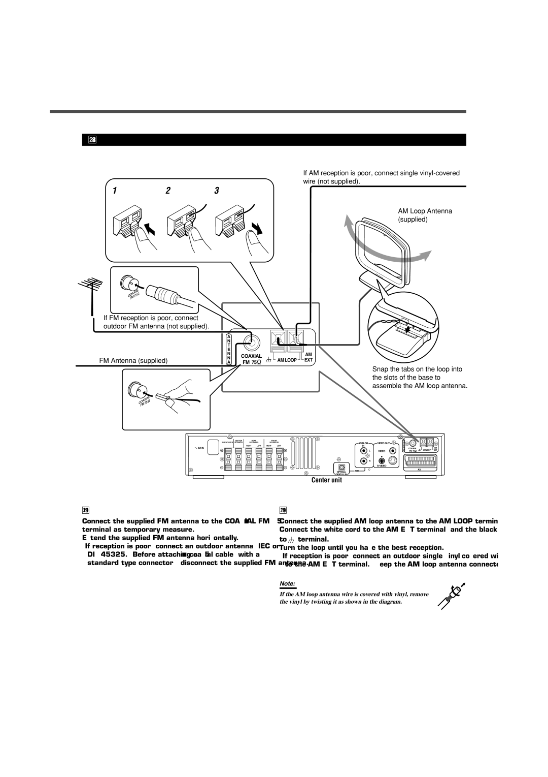
If AM reception is poor, connect single
1 | 2 | 3 |
AM Loop Antenna (supplied)
If FM reception is poor, connect outdoor FM antenna (not supplied).
FM Antenna (supplied)
A |
|
| |
N |
|
| |
T |
|
| |
E |
|
| |
N | COAXIAL |
| |
N | AM LOOP | ||
A | FM 75 | ||
|
AM
EXT
Snap the tabs on the loop into the slots of the base to assemble the AM loop antenna.
CENTER |
| REAR |
SUBWOOFER SPEAKER | SPEAKERS | |
| RIGHT | LEFT |
![]() AC IN
AC IN
FRONT
SPEAKERS
RIGHT LEFT
|
| A |
|
| |
ANALOG | VIDEO OUT | N |
|
| |
T |
|
| |||
IN |
| E |
|
| |
|
| N | COAXIAL | AM | |
L | VIDEO | N | AM LOOP EXT | ||
A | FM 75 | ||||
|
R
OPTICAL AUX
DIGITAL IN
Center unit
AV
FM antenna connection
Connect the supplied FM antenna to the COAXIAL FM 75 Ω terminal as temporary measure.
Extend the supplied FM antenna horizontally.
•If reception is poor, connect an outdoor antenna (IEC or DIN45325.) Before attaching a 75 Ω coaxial cable (with a standard type connector), disconnect the supplied FM antenna.
AM antenna connection
Connect the supplied AM loop antenna to the AM LOOP terminals. Connect the white cord to the AM EXT terminal, and the black cord to ![]() terminal.
terminal.
Turn the loop until you have the best reception.
•If reception is poor, connect an outdoor single
Note:
If the AM loop antenna wire is covered with vinyl, remove the vinyl by twisting it as shown in the diagram.
5