Names of parts and controls
The illustrations of the center unit and the subwoofer used in this manual are of
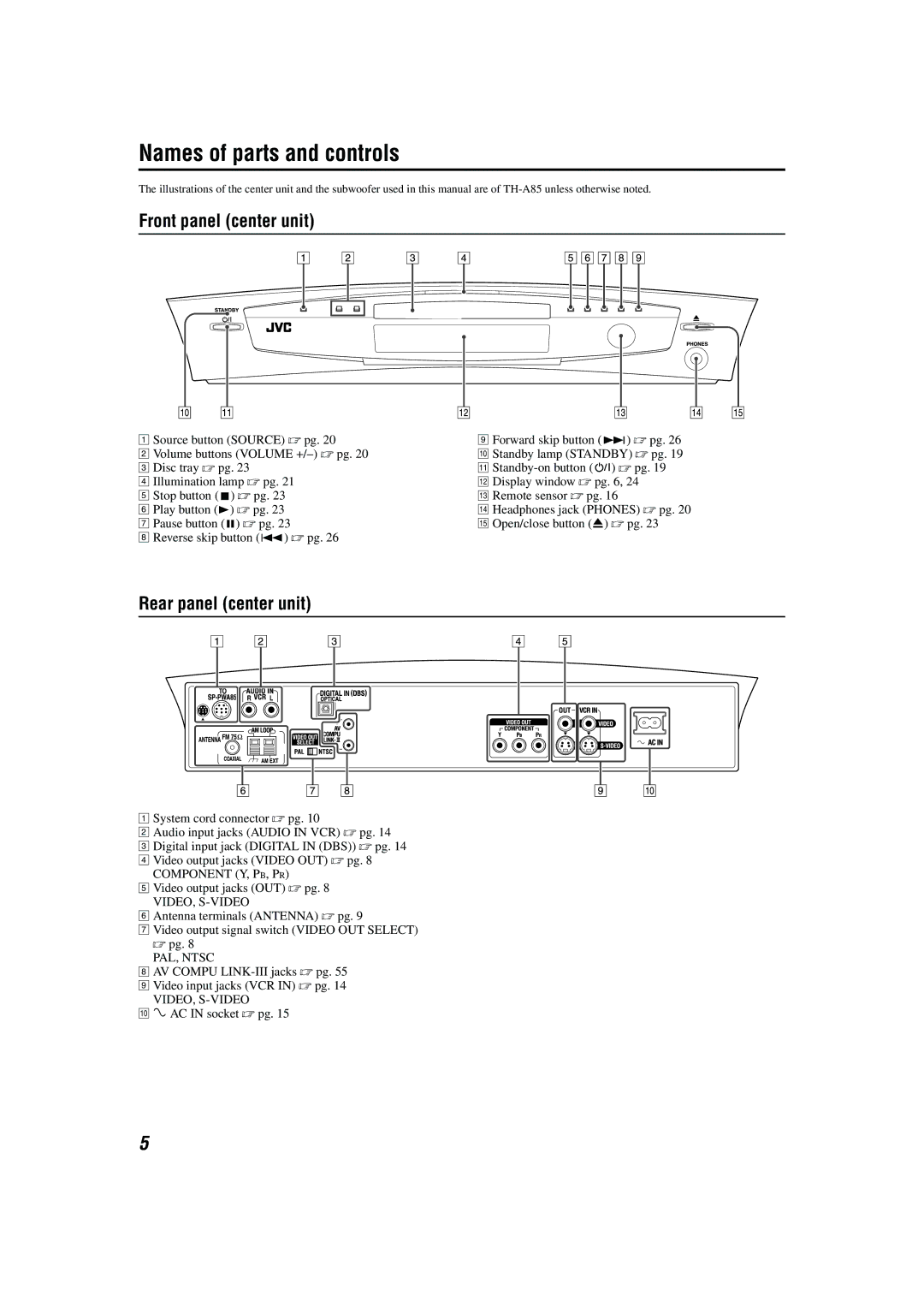
Front panel (center unit)
A Source button (SOURCE) A pg. 20
B Volume buttons (VOLUME
D Illumination lamp A pg. 21
EStop button (7) A pg. 23
FPlay button (3) A pg. 23
GPause button (8) A pg. 23
HReverse skip button (4) A pg. 26
IForward skip button (¢) A pg. 26
JStandby lamp (STANDBY) A pg. 19
K
LDisplay window A pg. 6, 24
MRemote sensor A pg. 16
NHeadphones jack (PHONES) A pg. 20
OOpen/close button (0) A pg. 23
Rear panel (center unit)
A System cord connector A pg. 10
B Audio input jacks (AUDIO IN VCR) A pg. 14 C Digital input jack (DIGITAL IN (DBS)) A pg. 14 D Video output jacks (VIDEO OUT) A pg. 8
COMPONENT (Y, PB, PR)
E Video output jacks (OUT) A pg. 8
VIDEO,
F Antenna terminals (ANTENNA) A pg. 9
G Video output signal switch (VIDEO OUT SELECT) A pg. 8
PAL, NTSC
HAV COMPU
IVideo input jacks (VCR IN) A pg. 14
VIDEO,
JÓAC IN socket A pg. 15
5