REAR VIEW
<Rear Panel>
| VIDEO |
A | B |
IN | IN |
| Y/C IN |
OUT | OUT |
AUDIO
A | B |
IN
OUT
[TM-A13UCV]
| VIDEO |
A | B |
IN | IN |
OUT | OUT |
To AC outlet
(120 V AC, 50/60 Hz)
| VIDEO |
| AUDIO |
A | B | A | B |
IN | IN |
|
|
| Y/C IN | IN |
|
OUT | OUT | OUT |
|
(Rear view of
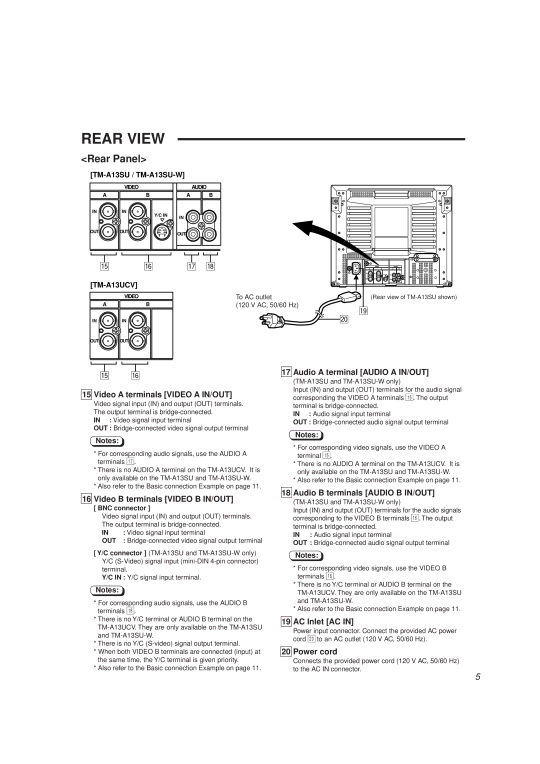
15 Video A terminals [VIDEO A IN/OUT]
Video signal input (IN) and output (OUT) terminals. The output terminal is
IN : Video signal input terminal
OUT :
Notes:
17 Audio A terminal [AUDIO A IN/OUT]
Input (IN) and output (OUT) terminals for the audio signal corresponding the VIDEO A terminals %. The output terminal is
IN : Audio signal input terminal
OUT :
Notes:
*For corresponding audio signals, use the AUDIO A terminals &.
*There is no AUDIO A terminal on the
*Also refer to the Basic connection Example on page 11.
16 Video B terminals [VIDEO B IN/OUT]
[ BNC connector ]
Video signal input (IN) and output (OUT) terminals. The output terminal is
IN | : Video signal input terminal |
OUT | : |
[ Y/C connector ]
Y/C IN : Y/C signal input terminal.
Notes:
*For corresponding audio signals, use the AUDIO B terminals *.
*There is no Y/C terminal or AUDIO B terminal on the
*There is no Y/C
*When both VIDEO B terminals are connected (input) at the same time, the Y/C terminal is given priority.
*Also refer to the Basic connection Example on page 11.
*For corresponding video signals, use the VIDEO A terminal %.
*There is no AUDIO A terminal on the
*Also refer to the Basic connection Example on page 11.
18 Audio B terminals [AUDIO B IN/OUT]
Input (IN) and output (OUT) terminals for the audio signals corresponding to the VIDEO B terminals ^. The output terminal is
IN : Audio signal input terminal
OUT :
Notes:
*For corresponding video signals, use the VIDEO B terminals ^.
*There is no Y/C terminal or AUDIO B terminal on the
*Also refer to the Basic connection Example on page 11.
19 AC Inlet [AC IN]
Power input connector. Connect the provided AC power cord ) to an AC outlet (120 V AC, 50/60 Hz).
20 Power cord
Connects the provided power cord (120 V AC, 50/60 Hz) to the AC IN connector.
5