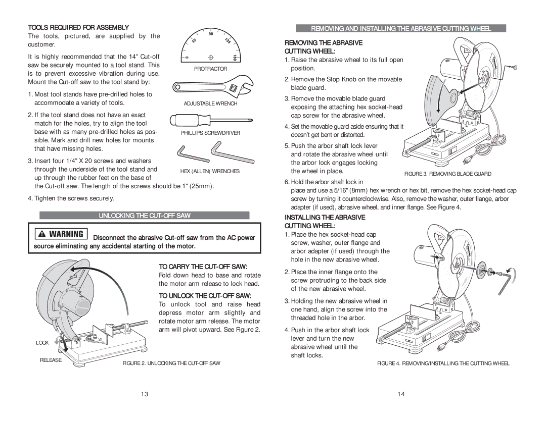
PROTRACTOR
ADJUSTABLE WRENCH
PHILLIPS SCREWDRIVER
HEX (ALLEN) WRENCHES

TOOLS REQUIRED FOR ASSEMBLY

The tools, pictured, are supplied by the customer.

It is highly recommended that the 14" Cut-off saw be securely mounted to a tool stand. This is to prevent excessive vibration during use. Mount the Cut-off saw to the tool stand by:

1. Most tool stands have pre-drilled holes to accommodate a variety of tools.

2.If the tool stand does not have an exact match for the holes, try to align the tool

base with as many pre-drilled holes as pos- sible. Mark and drill new holes for mounts that have missing holes.

3. Insert four 1/4" X 20 screws and washers through the underside of the tool stand and up through the rubber feet on the base of

the Cut-off saw. The length of the screws should be 1" (25mm).

4. Tighten the screws securely.

UNLOCKING THE CUT-OFF SAW

Disconnect the abrasive Cut-off saw from the AC power source eliminating any accidental starting of the motor.

TO CARRY THE CUT-OFF SAW: Fold down head to base and rotate the motor arm release to lock head.

TO UNLOCK THE CUT-OFF SAW: To unlock tool and raise head depress motor arm slightly and rotate motor arm release. The motor arm will pivot upward. See Figure 2.

LOCK

RELEASE

FIGURE 2. UNLOCKING THE CUT-OFF SAW


REMOVING AND INSTALLING THE ABRASIVE CUTTING WHEEL

REMOVING THE ABRASIVE CUTTING WHEEL:

1. Raise the abrasive wheel to its full open position.

2. Remove the Stop Knob on the movable blade guard.

3. Remove the movable blade guard exposing the attaching hex socket-head cap screw for the abrasive wheel.

4. Set the movable guard aside ensuring that it doesn’t get bent or distorted.

5. Push the arbor shaft lock lever

and rotate the abrasive wheel until


the arbor lock engages locking


the wheel in place.

FIGURE 3. REMOVING BLADE GUARD


6.Hold the arbor shaft lock in

place and use a 5/16" (8mm) hex wrench or hex bit, remove the hex socket-head cap screw by turning it counterclockwise. Also, remove the washer, outer flange, arbor adapter (if used), abrasive wheel, and inner flange. See Figure 4.

INSTALLING THE ABRASIVE CUTTING WHEEL:

1. Place the hex socket-head cap screw, washer, outer flange and arbor adapter (if used) through the hole in the new abrasive wheel.

2. Place the inner flange onto the screw protruding to the back side of the new abrasive wheel.

3. Holding the new abrasive wheel in one hand, align the screw into the threaded hole in the arbor.

4. Push in the arbor shaft lock lever and turn the new abrasive wheel until the shaft locks.

FIGURE 4. REMOVING/INSTALLING THE CUTTING WHEEL

13

14

Page 8
Image 8
Kawasaki 691204 Tools Required for Assembly, Tools, pictured, are supplied by the customer, Unlocking the CUT-OFF SAW

691204 specifications

The Kawasaki 691204 is a powerful engine designed for a variety of heavy-duty applications, specifically in the domain of outdoor power equipment. This engine exemplifies Kawasaki’s commitment to performance, reliability, and advanced technology, making it a preferred choice for both commercial and residential users.

One of the main features of the Kawasaki 691204 is its impressive horsepower output, which is optimized for tasks requiring significant power such as lawn care, landscaping, and industrial applications. Its robust design allows it to handle even the toughest jobs with efficiency, ensuring that users achieve their desired outcomes without prolonged downtime.

The Kawasaki 691204 incorporates cutting-edge technology, including an overhead valve (OHV) design. This feature not only improves the engine's overall efficiency but also enhances its torque curve, allowing for better performance at various operating speeds. The OHV configuration also contributes to lower emissions, aligning the engine with modern environmental standards and regulations, making it an eco-friendly option without compromising power.

Another significant characteristic of the Kawasaki 691204 is its exceptional durability. Constructed from high-quality materials, this engine is built to withstand demanding conditions and extended use. The engine’s enhanced cooling system ensures optimal operating temperatures, reducing the risk of overheating and prolonging its lifespan. Moreover, the 691204 is designed for easy maintenance, featuring accessible components that streamline servicing tasks, thus enhancing user convenience.

Furthermore, the Kawasaki 691204 is known for its smooth operation. Thanks to the advanced balancing technology integrated into the engine, vibrations are minimized, resulting in a more comfortable user experience. This is particularly important for extended usage, as it reduces fatigue and increases productivity.

In summary, the Kawasaki 691204 is an outstanding engine characterized by its power, efficiency, and durability. Equipped with advanced technologies such as the OHV design and a high-performance cooling system, it meets the demands of both commercial and residential users alike. With its user-friendly maintenance features and smooth operation, the Kawasaki 691204 stands out as a reliable choice for those seeking a high-performance engine to tackle a wide variety of outdoor power equipment tasks.